Device comprising a communications stack with a scheduler

US20050223191A1Inactive Publication Date: 2005-10-06RADIOSCAPE

Image

  • Device comprising a communications stack with a scheduler
  • Device comprising a communications stack with a scheduler
  • Device comprising a communications stack with a scheduler

Examples


Embodiment Construction

[0033] The present invention will be described with reference to an implementation from Radioscape Ltd of London, United Kingdom: the CVM (communication virtual machine).

1. Overview of Predictive Scheduling

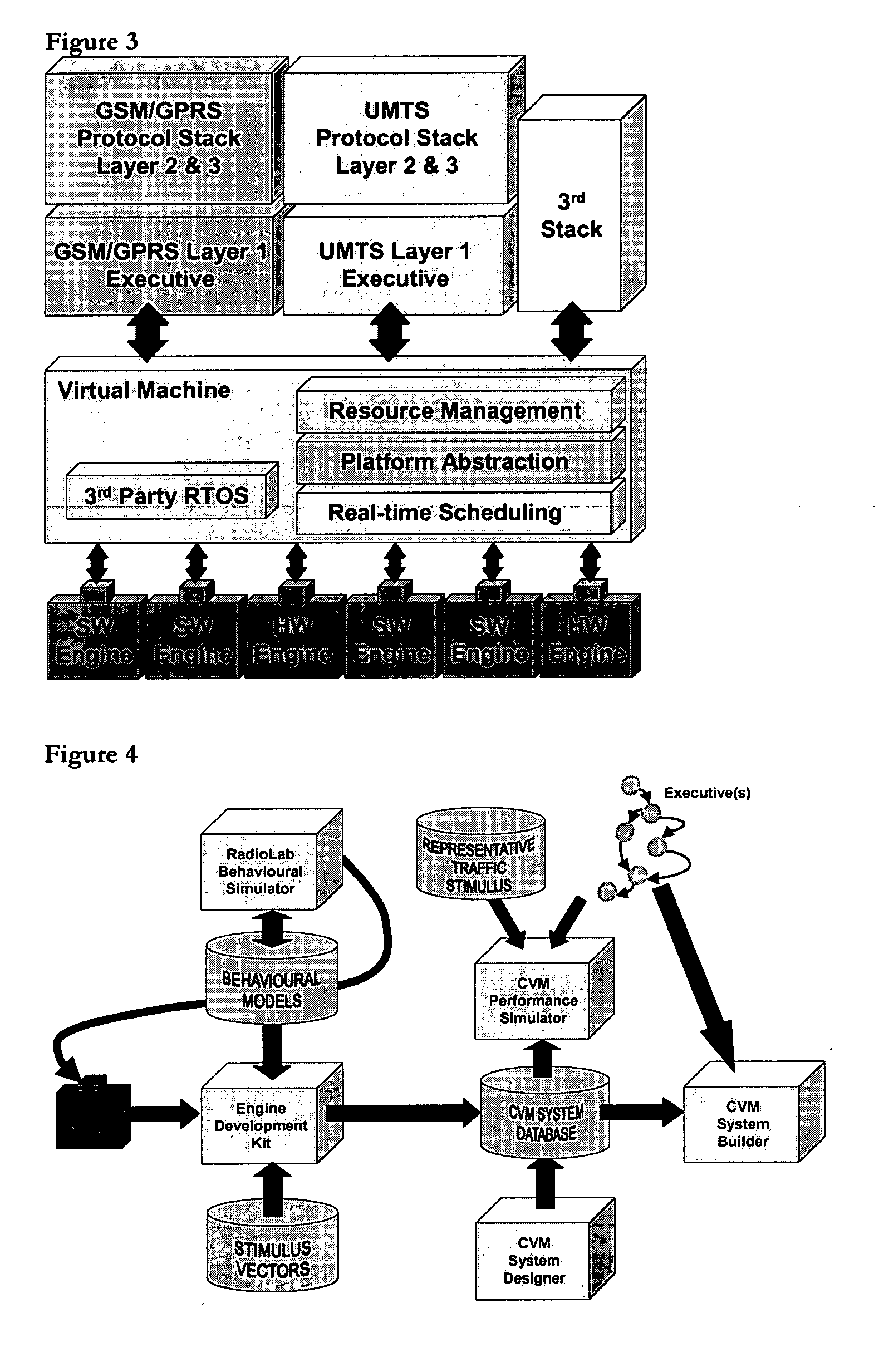
[0034] We believe that the use of predictive scheduling policies, coupled to the CVM runtime and design and simulation tools, provides a valid solution to the multimode problem (i.e. where we have a number of independent executives, which must be scheduled over a single physical thread), while not sacrificing overall system efficiency.

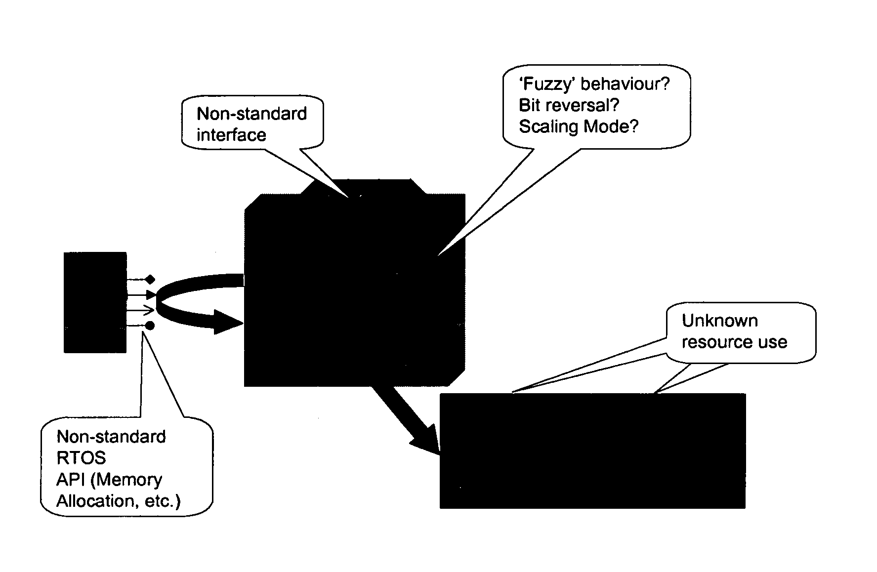
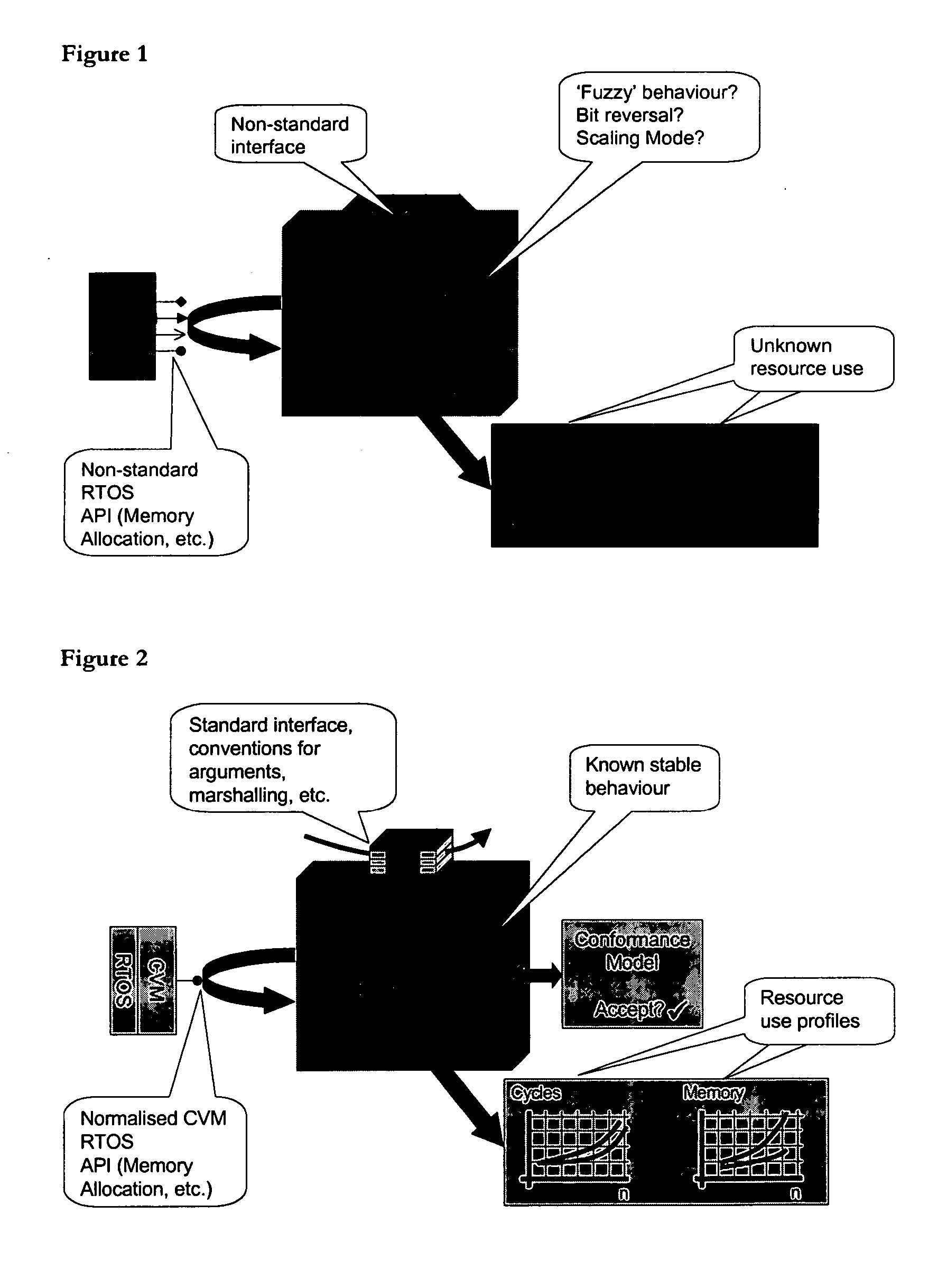
[0035] Under the CVM, a communications stack is split up into engines (high resource transforms, which are either implemented in custom hardware or in DSP assembly code), and executives (the rest of the software, written in a hardware-neutral language such as C). Engines must utilise a standard argument-passing format, conform in behaviour to a published model, and provide a resource utilisation profile of themselves (for memory, cycles etc.). Al...


PUM


Abstract

A scheduler is used to schedule execution of tasks by ‘engines’ that perform high resource functions as requested by ‘executive’ control code, the scheduler using its knowledge of the likelihood of engine request state transitions. The likelihood of engine request state transitions describes the likely sequence of engines which executives will impose: the scheduler can at run-time in effect, as the start of a time slice, look-forward in time to discern a number of possible schedules (i.e. sequence of future engines), assess the merits of each possible schedule using pre-defined parameters (e.g. memory and power utilisation), then apply the schedule which is most appropriate given those parameters. The process repeats at the start of the next time slice. The scheduler therefore operates as a predictive scheduler. The present invention is particularly effective in addressing the “multi-mode problem”: dynamically balancing the requirements of multiple communications stacks operating concurrently.

Description

BACKGROUND OF THE INVENTION [0001] 1. Field of the Invention [0002] This invention relates to a device comprising a communications stack, the stack including a scheduler. The device performs real-time DSP or communications activities. [0003] 2. Description of the Prior Art [0004] Modern communications systems are increasingly complex, and this fact is threatening the ability of companies to bring such products to market at all. The pressure has been felt particularly by the manufacturers of user equipment terminals (colloquially, ‘UEs’) in the wireless telecommunications space. These OEMs now find that they must integrate multiple, packet-based standards (coming, in all likelihood, from a number of independent development houses) together on an underlying hardware platform, within an ever-shortening time-to-market window, without violating a relatively constrained resource profile (memory, cycles, power etc.). We refer to this unenviable predicament as the ‘multimode problem’. [0005...

Claims


Application Information

Patent Timeline
06 Oct 2005
Publication
US20050223191A1
IPC
G06F9/455; G06F9/48; G06F17/50
CPC
G06F9/45537; G06F9/4887; G06F17/5045; G06F30/30
Inventors
FERRIS, GAVIN ROBERT