Luminescent vest equipped with plastic optical fibers

a technology of optical fibers and luminescent vests, which is applied in the direction of fibre light guides, cladding optical fibres, instruments, etc., can solve the problems of high cost, potential casualties, and the danger of traffic accidents of light-emitting diodes, and achieve the effect of low cost and low power

Inactive Publication Date: 2005-10-13
BAYCOM OPTO ELECTRONICS TECH
View PDF5 Cites 18 Cited by
  • Summary
  • Abstract
  • Description
  • Claims
  • Application Information

AI Technical Summary

Benefits of technology

[0003] It is the objective of this invention to provide a luminescent vest equipped with plastic optical fibers, installed with luminescent woven layers at specified locations on the back and front of the vest, and consisting of three structural layers. The top layer is a plastic film that has letters or patterns on the surface that project light. The middle layer is a woven layer, including (1) plastic optical fibers woven lengthwise and chemical fibers woven crosswise; (2) plastic optical fibers woven crosswise and chemical fibers woven lengthwise; and (3) plastic optical fibers woven lengthwise and crosswise. The bottom layer is a web-like woven layer. The aforementioned vest has three structural layers, where light is emitted for alarm effects. The present invention has the following features: (1) the lighting is made from plastic optical fibers that consume low power without generating heat, so they can be safety attached to woven fabrics; (2) the present invention is suitable for mass production at low cost.

Problems solved by technology

Without a luminescent vest at night, joggers or pedestrians may face the danger of a traffic accident.
That could be a recipe for disaster, causing an accident and potential casualty due to a lack of alarm.
But such light-emitting diodes have a risk of burning out and the shortcoming of higher costs.

Method used


Image

  • Luminescent vest equipped with plastic optical fibers
  • Luminescent vest equipped with plastic optical fibers
  • Luminescent vest equipped with plastic optical fibers

Examples


Embodiment Construction

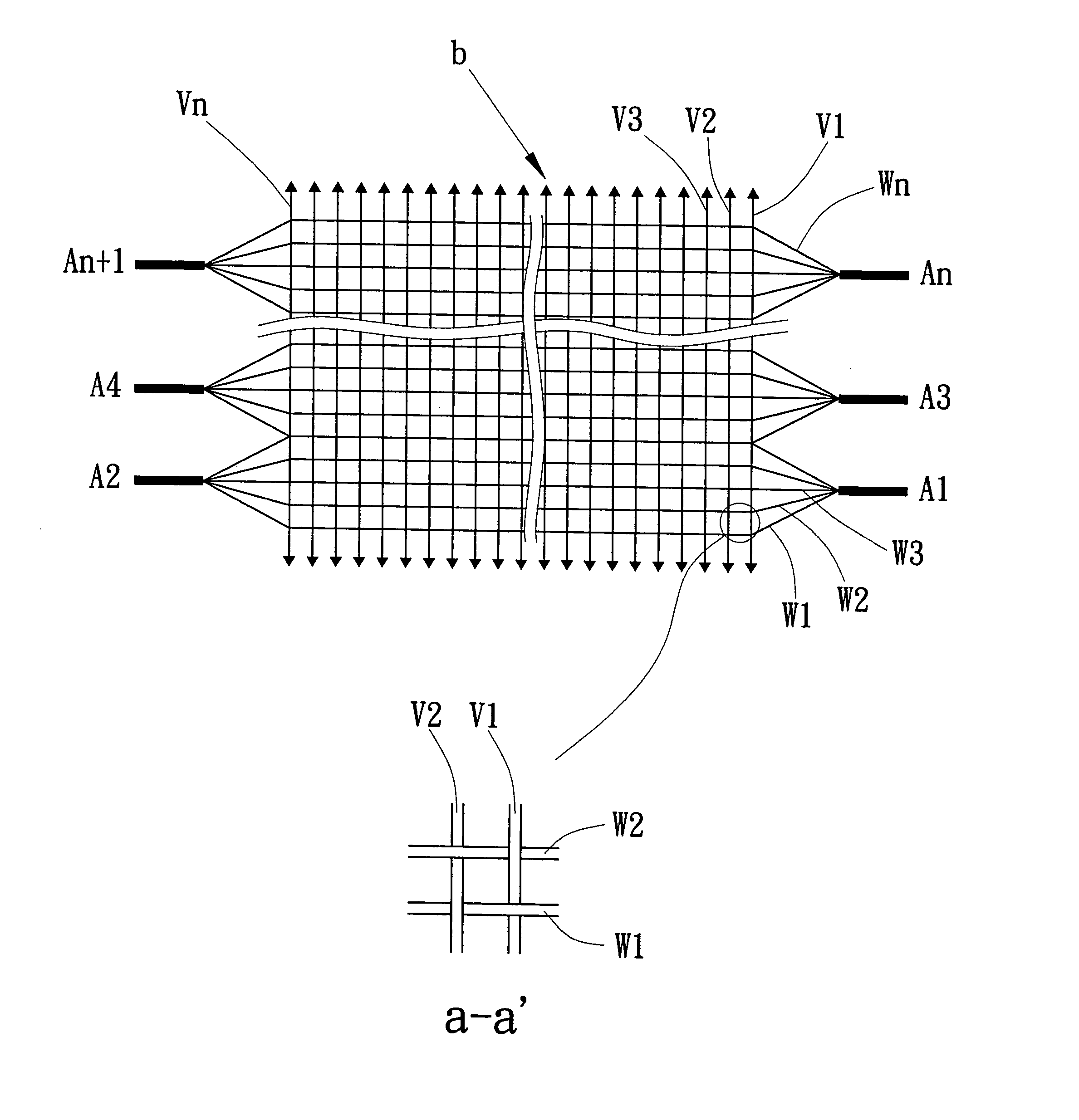
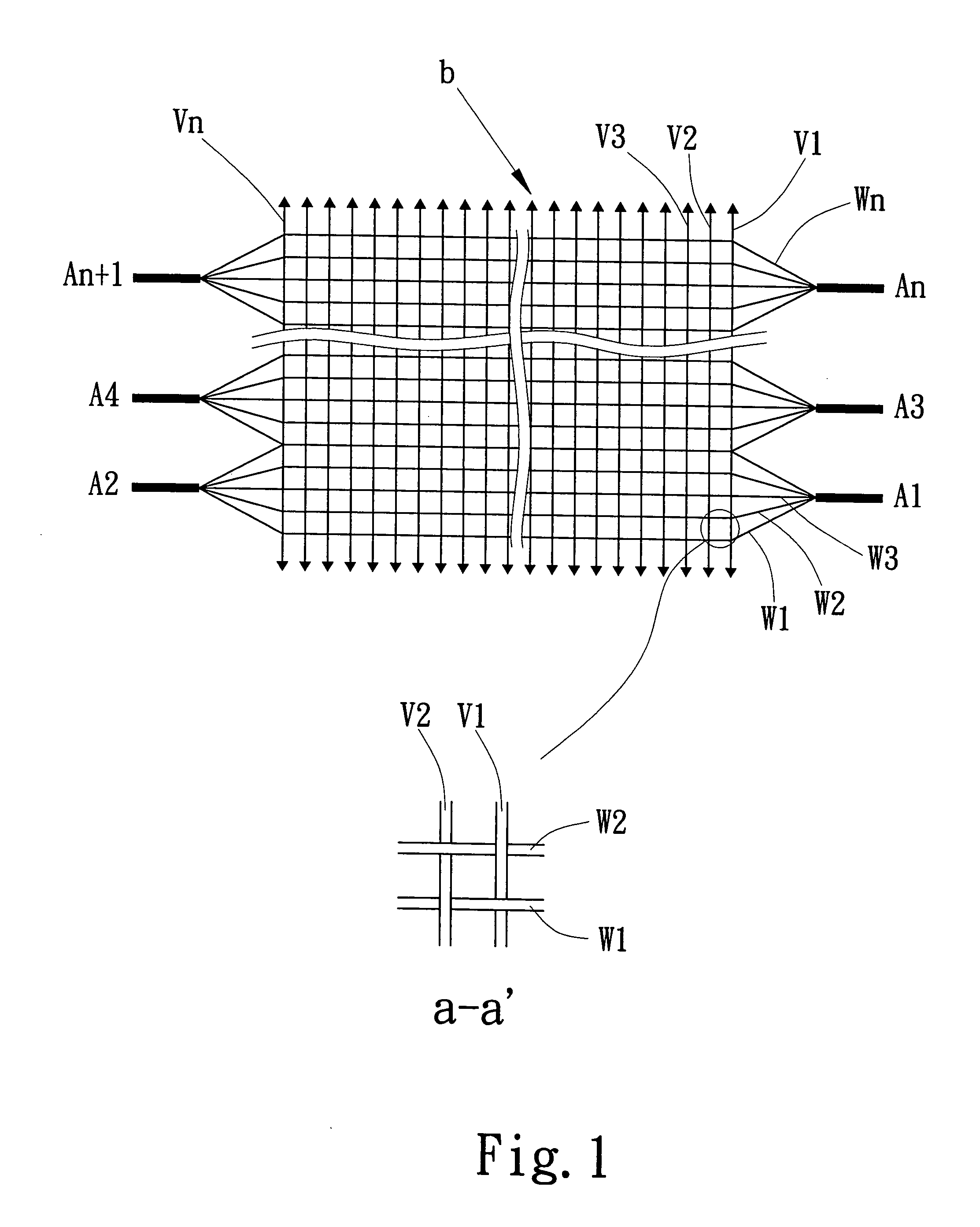
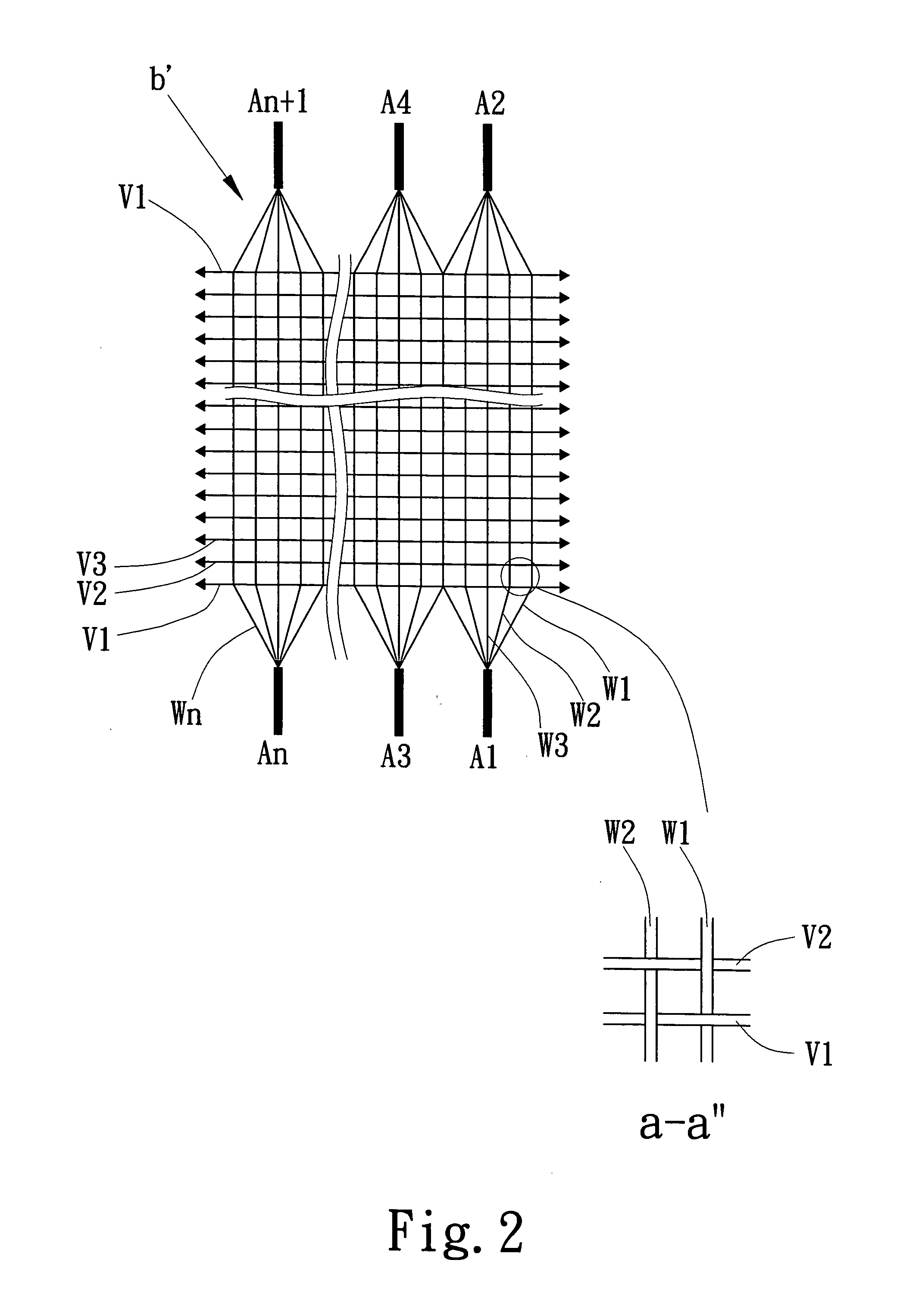
[0014] As shown in the drawings, the present invention is a vest equipped with luminescent plastic optical fibers. The vest 1 has a front side 11 and a rear side 12, wherein the front side 11 has light-emitting units 111 and 112, and the rear side 12 has a light-emitting unit 121, as shown in FIGS. 6 and 7. The light-emitting units 111, 112, 121 on the front side 11 and the rear side 12 are three structural layers: top layer, middle layer and bottom layer, as shown in FIG. 5. They include the top layer which is a plastic film layer a, made of PP, PVC, PET or any highly transparent plastic films, adhered to the woven layer b in the middle layer. On the surface of the plastic film layer a are letters or patterns according to design. The letters or patterns are transparent, serving to emit light. The middle layer of woven layer b includes: (1) the middle layer of woven layer b consisting of plastic optical fibers W1, W2, W3 . . . and Wn running lengthwise and interwoven with chemical f...


PUM


Abstract

A luminescent vest equipped with plastic optical fibers having structural layers including a top layer of plastic film, a middle layer of plastic optical fibers and a bottom layer of a web-like structure. The middle woven layer has the following woven structure: (1) interwoven by lengthwise plastic optical fibers and crosswise plastic optical fibers; (2) interwoven by crosswise chemical fibers and lengthwise plastic optical fibers; (3) interwoven by lengthwise chemical fibers and crosswise plastic optical fibers. The three-layer structure is distributed at appropriate positions on the vest, while the top part of plastic film layer is arranged with letters or patterns serving to project light from the plastic optical fibers, and connected to electrical power to project alarm light effects. The present invention can be used in applications that include a traffic policeman's uniform, an environmental protection worker's uniform, a security guard's uniform and ordinary apparel.

Description

1. FIELD OF THE INVENTION [0001] The present invention relates to a luminescent vest equipped with plastic optical fibers, particularly to a luminescent vest equipped with a middle layer of light-emitting woven fabric, to attract people's attention and ensure better safety. 2. BACKGROUND OF THE INVENTION [0002] With the increase of traffic flow, people on the road like road workers, traffic policemen, road sweepers and ordinary pedestrians, need better protection by wearing a luminescent vest, especially at night when motorists can not see very well. Without a luminescent vest at night, joggers or pedestrians may face the danger of a traffic accident. For this reason, there is a readily available vest on the market, which is equipped with light-reflecting strips that reflect light only when there is a light source projected onto the vest. Yet, this type of vest does not emit light by itself. The motorist cannot see the person wearing the vest until the car is within a very short dis...

Claims


Application Information

Patent Timeline
Patent Type & Authority Applications(United States)
IPC IPC(8): A41D1/04A41D13/01A41D27/08F21V8/00G02B6/02G02B6/04
CPCA41D13/01A41D27/085A41D2500/20G02B6/001G02B6/04
Inventor HUANG, JYH-PERNGWANG, CHIEN-TANG
Owner BAYCOM OPTO ELECTRONICS TECH
Why Eureka
Try Eureka