Circumferential sealing diaphragm valve

a diaphragm valve and circumferential sealing technology, applied in the direction of diaphragm valves, engine diaphragms, functional valve types, etc., can solve the problems of significant risk, insufficient cleaning of equipment in these processes, and insufficient procedures executed

Inactive Publication Date: 2005-10-13
NL TECH
View PDF22 Cites 15 Cited by
  • Summary
  • Abstract
  • Description
  • Claims
  • Application Information

AI Technical Summary

Benefits of technology

[0016] Having described the strengths and weaknesses of the two predominant categories of valves used for hygienic processing, the present inventor would like to present a new alternative valve design that combines the best features of each of the design categories discussed above, while eliminating weaknesses. As will be seen in the present invention, it is possible to construct a valve design that can incorporate the desirable diaphragm sealing component wherein the dynamic seal is segregated from the static circumferential seal, where the process contact surfaces of the valve body and of the diaphragm are fully accessible to the process flow without the creation of pooling areas, breathing seals or additional crevice areas so that cleaning and sterilizing the valve in place can most effectively be achieved.
[0017] The present invention has the added benefit of being a compact design that may also be manufactured economically due, in part, to the open nature of the internal cavity and passages formed in the valve body. Furthermore, when constructed as an embodiment where inlet and outlet passages are coaxial, the present invention has the benefit of being bilaterally symmetrical, allowing it to be used, without modification and without any loss in operational effectiveness, in right- or left-handed applications, requiring only that the body be rotated. The valve of the present invention also provides improved flow with better self-cleaning and sterilizing characteristics because of the minimization of quiet zones and the sweeping scouring flow path that will be created as material flows into and out of the internal valve cavity.
[0018] It is a primary object of the present invention to provide a device that can be effectively cleaned and sterilized in place, where the process can effectively be isolated from the mechanical valve elements through the use of a diaphragm or other effective sealing members and where unobstructed free-drainage through the valve can still be achieved.

Problems solved by technology

Among the concerns are that some equipment in these processes may not be adequately cleanable in place, that in-situ cleaning procedures are not themselves adequate to clean the equipment installed or that the procedures and equipment are appropriately matched, but the procedures are not being properly executed.
While still the preferred choice for some applications, it has become apparent that weir diaphragm valves can pose a significant risk as a source of cross over contamination, particularly if improperly installed, operated and maintained or if clean-in-place and sterilize-in-place procedures are not properly followed.
The main problem with the weir diaphragm valve design is that the static circumferential seal 136 is continuous with the line seal 137 made by the diaphragm 133 across the top of the weir 140.
Although this may be less of a problem while a batch of a process is in progress, not completely removing the trapped residual during cleaning procedures between batches is a more serious issue and may be considered very critical between campaigns of different products by the FDA.
This of course causes cross contamination.
While this is necessary in order to make weir valves drain, this also places a portion of the circumferential seal 136 at the bottom of the valve, causing it to become a sump where material will tend to collect and where complete drainage will be very difficult to fully achieve.
Consequently, a more significant cleaning challenge and possible point source for cross contamination is exacerbated when using a weir valve in this manner.
While it would seem that the solution to the cross contamination problems currently plaguing the industry could be resolved by radial diaphragm valves, it is a byproduct of the radial design that makes radial diaphragm valves a less perfect solution to the problem.
As can be readily understood, since radial diaphragm valves are only completely drainable if oriented in a vertical manner, there are severe limitation on how radial diaphragm valves found in the background are can effectively be used.
Specifically, orienting a radial diaphragm valve in a vertical orientation results in a significant vertical drop across them.
Due to the numerous valves required for some systems, orienting all of the valves in a vertical manner is not possible because of the space limitations.

Method used


Image

  • Circumferential sealing diaphragm valve
  • Circumferential sealing diaphragm valve
  • Circumferential sealing diaphragm valve

Examples


Embodiment Construction

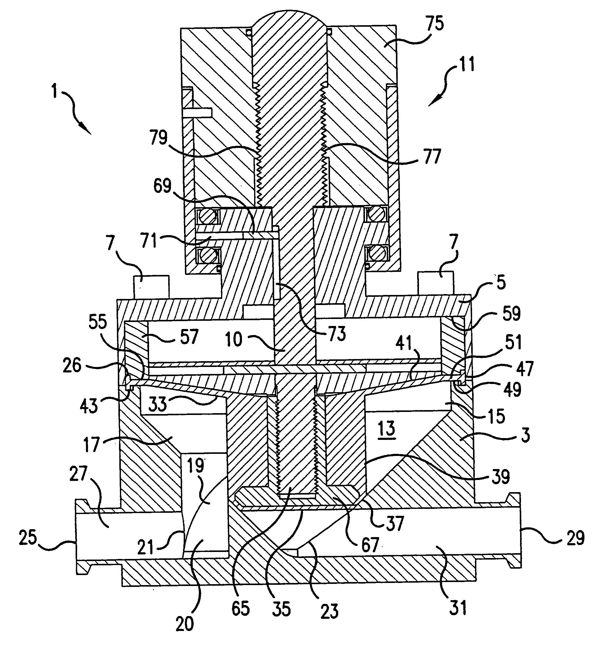
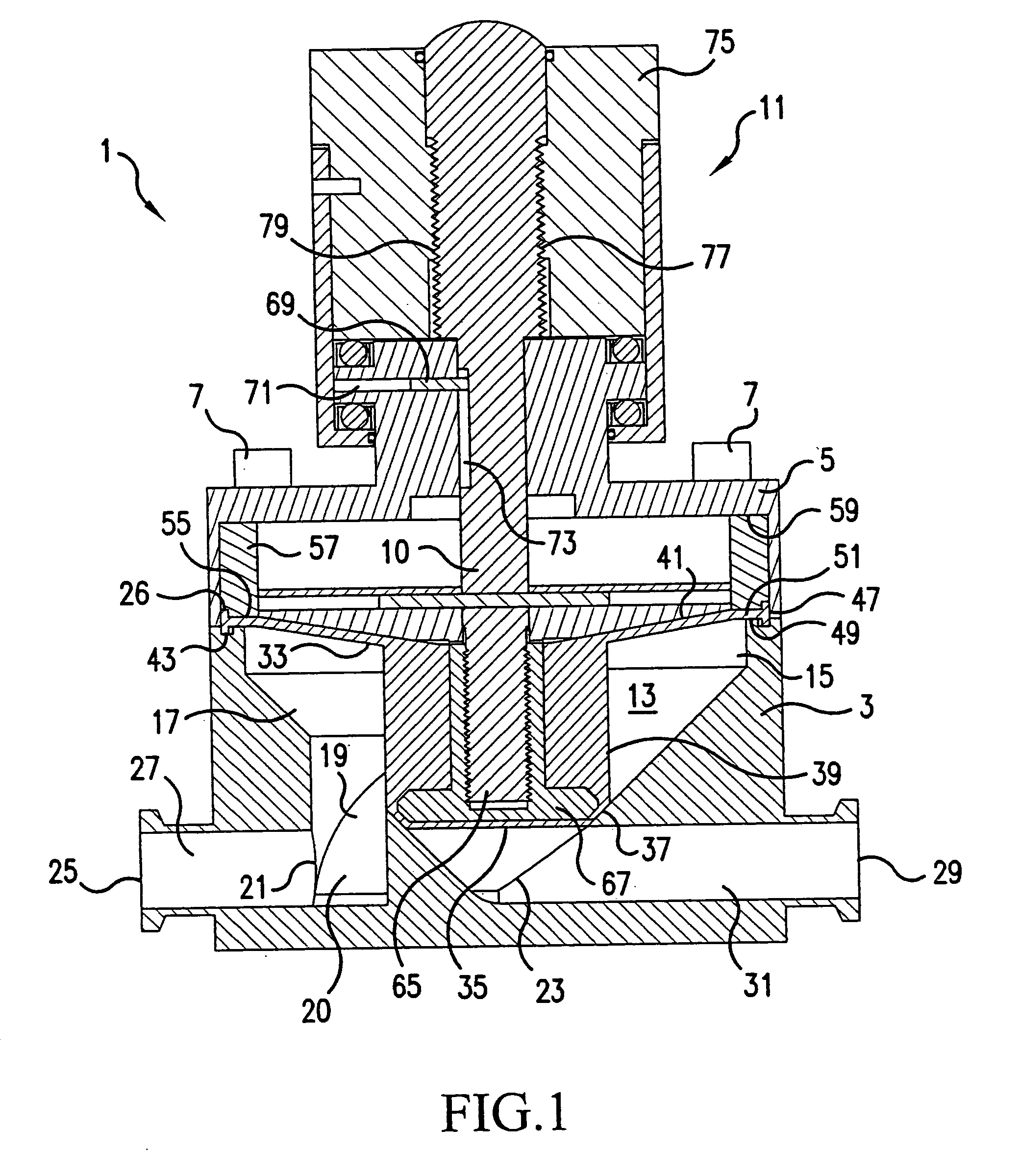
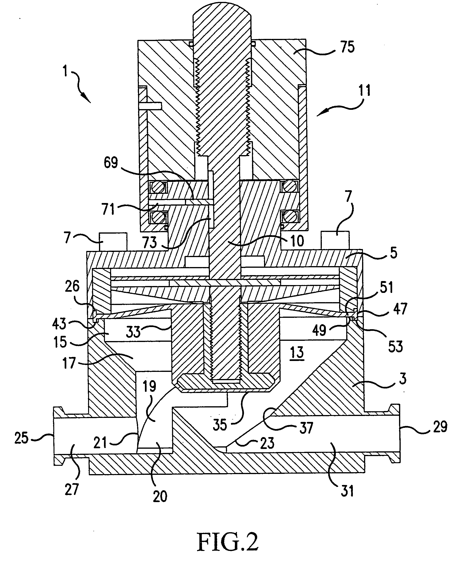
[0042] The present invention will now be described with reference to the accompanying drawings. Referring to FIGS. 1-5, a first embodiment of the present invention will be described. FIGS. 1 and 2 are vertical cross-sections through the valve 1 of the present invention. FIG. 1 illustrates the valve in a closed position and FIG. 2 illustrates the valve in an open position.

[0043] The valve 1 includes a valve body 3 and a bonnet 5. The bonnet 5 can be connected to the valve body 3 through numerous types of mechanisms including clamps, etc. However, in FIGS. 1-5, the bonnet 5 is illustrated as being connected to the valve body 3 by a plurality of bolts 7 which extend into corresponding bolt holes 9 formed in the bonnet 5 and the valve body 3 (see FIG. 3).

[0044] The valve 1 also includes a valve actuator rod 10 mounted in the bonnet 5. In FIGS. 1 and 2, the valve actuator rod 10 is illustrated with a manual actuator 11 for opening and closing the valve. However, it should be understood...


PUM


Abstract

A valve body for a valve includes a body having an internal cavity formed therein. An inlet passage and an outlet passage are formed in the body. The inlet passage has an inlet opening in communication with the internal cavity, and the outlet passage has an outlet opening in communication with the internal cavity. A circumferential sealing surface is formed on a wall of the internal cavity. The circumferential sealing surface extends between the inlet opening and the outlet opening and circumferentially around the internal cavity. Furthermore, a bottom line extending through the inlet passage, the internal cavity and the outlet passage forms a coplanar surface to allow for free-drainage of the body.

Description

CROSS-REFERENCE TO RELATED APPLICATIONS [0001] This application is a Continuation of co-pending application Ser. No. 10 / 921,805, filed on Aug. 20, 2004, which is a Continuation of U.S. application Ser. No. 10 / 077,878, filed Feb. 20, 2002, now U.S. Pat. No. 6,786,470. This application also claims priority under 35 U.S.C. § 119(e) on U.S. Provisional Application No. 60 / 269,335, filed Feb. 20, 2001. The entirety of each of the above-identified applications is hereby incorporated by reference.BACKGROUND OF THE INVENTION [0002] 1. Field of the Invention [0003] The present invention relates to diaphragm valves. In particular, the present invention relates to diaphragm valves which allow for free-drainage of a valve body of the valve when the valve is in the open position. [0004] 2. Description of Background Art [0005] The demand for higher quality products forces industries to continually re-evaluate fundamental and basic elements of their processes in a search to discover new methods and...

Claims


Application Information

Patent Timeline
Patent Type & Authority Applications(United States)
IPC IPC(8): F16K1/00F16K1/36F16K7/16
CPCF16K1/36F16K7/16
Inventor NEWBERG, DOUGLAS A.
Owner NL TECH
Why Eureka
Try Eureka