Flexible graphite sealing joint with metal jacket for high temperature

a graphite sealing joint and flexible technology, applied in the field of static tightness, can solve the problem that the replacement of asbestos with graphite has not yet solved the problem of the sealing join

Active Publication Date: 2005-10-13
COMMISSARIAT A LENERGIE ATOMIQUE ET AUX ENERGIES ALTERNATIVES +1
View PDF7 Cites 3 Cited by
  • Summary
  • Abstract
  • Description
  • Claims
  • Application Information

AI Technical Summary

Benefits of technology

[0001] The invention relates to the field of static tightness, particularly for pipe flanges likely to convey fluids at very high temperatures.

Problems solved by technology

Replacing the asbestos with the graphite has nevertheless not solved a problem relating to the variety of performance levels observed with these > seals, i.e. in connecting graphite and metal.

Method used


Image

  • Flexible graphite sealing joint with metal jacket for high temperature
  • Flexible graphite sealing joint with metal jacket for high temperature
  • Flexible graphite sealing joint with metal jacket for high temperature

Examples


Embodiment Construction

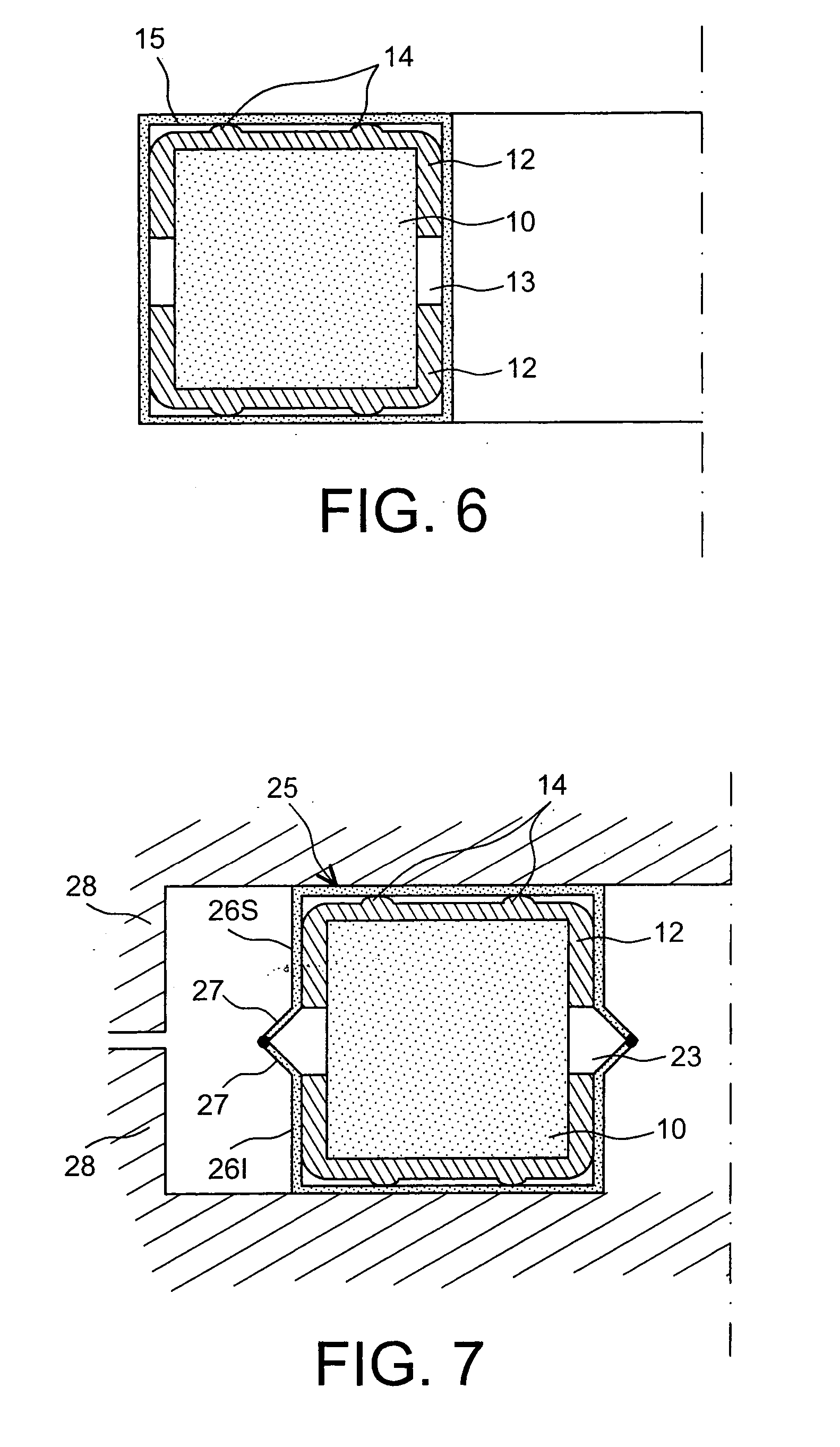
[0033] With reference to FIG. 6, the seal according to the invention is therefore a composite seal linking a flexible internal core 10, composed of expanded graphite or a material that is roughly equivalent. It is specified that, to preserve its elastic properties beyond 550° C. the expanded graphite must be maintained in an atmosphere free of oxygen. This is why, according to the invention, an hermetically sealed sheath 15 is produced, so as to prevent any migration of corrosive gas towards the graphite. It is anticipated that it may be possible to extract oxygen if necessary and replace it by a neutral gas like argon for example.

[0034] Thus the sheath 15 constitutes a metal box that obstructs any transfer of gas from the outside of this box thus constituted towards the inside, and vice versa. The flexible core 10 in expanded graphite is conditioned between the two metal cups 12 constituting the metal envelope, the volume of this core being thus demarcated to prevent any extrusion...


PUM

PropertyMeasurementUnit
temperatureaaaaaaaaaa
temperaturesaaaaaaaaaa
temperatureaaaaaaaaaa

Abstract

The seal can be used at high temperature. It is composed of a central flexible graphite core (10) maintained in its shape by two metal cups (12) that do not touch. It is all surrounded by a tight sheath (15) enabling the flexible core (10) to be maintained in a neutral atmosphere such as a partial vacuum or a neutral gas.

Description

SCOPE OF THE INVENTION [0001] The invention relates to the field of static tightness, particularly for pipe flanges likely to convey fluids at very high temperatures. PREVIOUS TECHNOLOGY AND PROBLEM POSED With reference to FIGS. 1, 2, 3, 4 and 5, several types of seal are known that use several materials such as metal and graphite. [0002]FIG. 1 shows the first, <<fluted>> type of seal, where a metallic core 1B is surrounded by two thin layers of graphite 1A. The metallic core 1B has flutes on its surface so that the graphite layers 1A can penetrate slightly into the metallic core 1B so as to result in the tightening of the joint. [0003]FIG. 2 shows a second, <<wavy>> type of seal where a central metal layer 2B with a wavy shape is covered on its two surfaces by a graphite layer 2A, also adopting the wavy shape. [0004]FIG. 3 shows a third, <<spiralled>> type of seal where a graphite spiral 3A is wrapped together with a metal spiral 3B. [0005]FIG. 4...

Claims


Application Information

Patent Timeline
Patent Type & Authority Applications(United States)
IPC IPC(8): F16J1/00F16J15/10F16J15/12
CPCF16J15/128
Inventor CAPLAIN, PHILIPPEROUAUD, CHRISTIANLE GALLO, PATRICKLE GUYADEC, FABIENNELEFRANCOIS, MICHELGENTZBITTEL, JEAN-MARIELEVOY, RICHARD
Owner COMMISSARIAT A LENERGIE ATOMIQUE ET AUX ENERGIES ALTERNATIVES
Why Eureka
Try Eureka