Rotor for brushless motor and brushless motor

a rotor and motor technology, applied in the direction of dynamo-electric components, dynamo-electric machines, magnetic circuit shapes/forms/construction, etc., can solve the problems of reducing the reliability of the magnet piece against scattering, weakened adhesion strength, and scattered pieces, so as to achieve the effect of reducing manufacturing costs

Inactive Publication Date: 2005-10-13
ICHINOMIYA ELECTRIC
View PDF8 Cites 35 Cited by
  • Summary
  • Abstract
  • Description
  • Claims
  • Application Information

AI Technical Summary

Benefits of technology

[0009] The present invention is made by taking the points mentioned above into consideration, and an object of the present invention is to provide a means which can securely prevent an idle running and a scattering of a magnet while restricting a manufacturing cost as low as possible, in a rotor used in a brushless motor.

Problems solved by technology

However, in the segment type, an adhesive strength is weakened due to a temperature increase, and there is a risk that the magnet piece is scattered in a centrifugal direction on the basis of the rotation of the rotor, and there is a problem that a reliability of the magnet piece against the scattering is lowered if the number of the magnetic poles of the rotor is increased.
However, in order to arrange the metal cylinder body, it is necessary to make a magnetic gap between the magnet piece and stator wide, so that there is a problem that a performance of the motor is lowered.
Further, there is a problem that an eddy current is generated in the metal cylinder body and a motor efficiency is lowered.
In the magnet interior type, since the rotor yoke exists in an outer side of the magnet piece in the same manner, the magnetic gap becomes wide, and since the rotor yoke exists between the magnet pieces, all magnetic fluxes of the magnetic pieces do not make their way to the stator side, and the magnetic fluxes leak to the other magnet pieces in both sides via the rotor yoke, so that there is a problem that the performance of the motor is lowered.
However, if the adhesive strength is weakened even in the case of employing the ring magnet, there is generated a problem that an idle running is generated with respect to the rotor yoke.
However, in the case where the protruding portion, the recess portion and the like for fitting to the rotor yoke are formed in the inner periphery of the ring magnet as mentioned above, it is necessary to finish these protruding portion and the like in a desired dimensional precision, so that there is a problem that the grinding step becomes complicated, and a manufacturing cost is increased.

Method used


Image

  • Rotor for brushless motor and brushless motor
  • Rotor for brushless motor and brushless motor
  • Rotor for brushless motor and brushless motor

Examples


Embodiment Construction

[0028] A description will be specifically given below of an embodiment in accordance with the present invention with reference to the accompanying drawings.

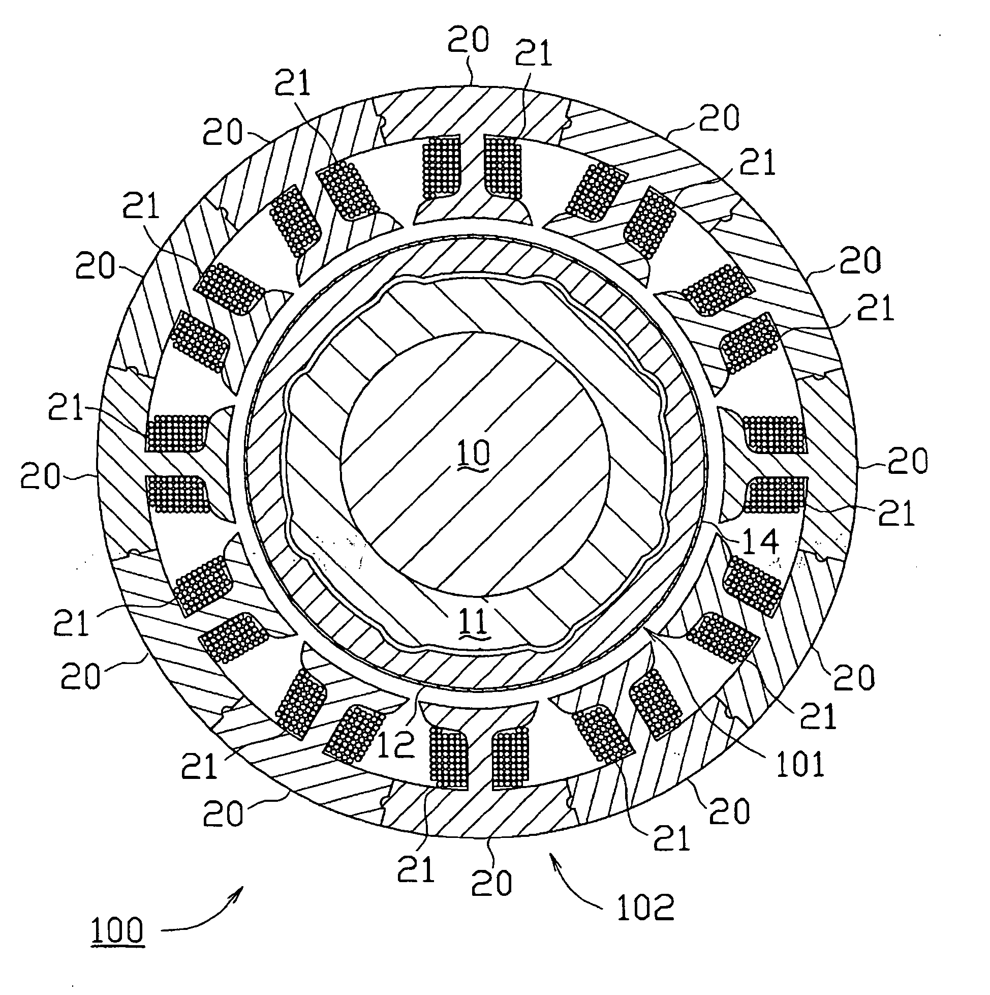
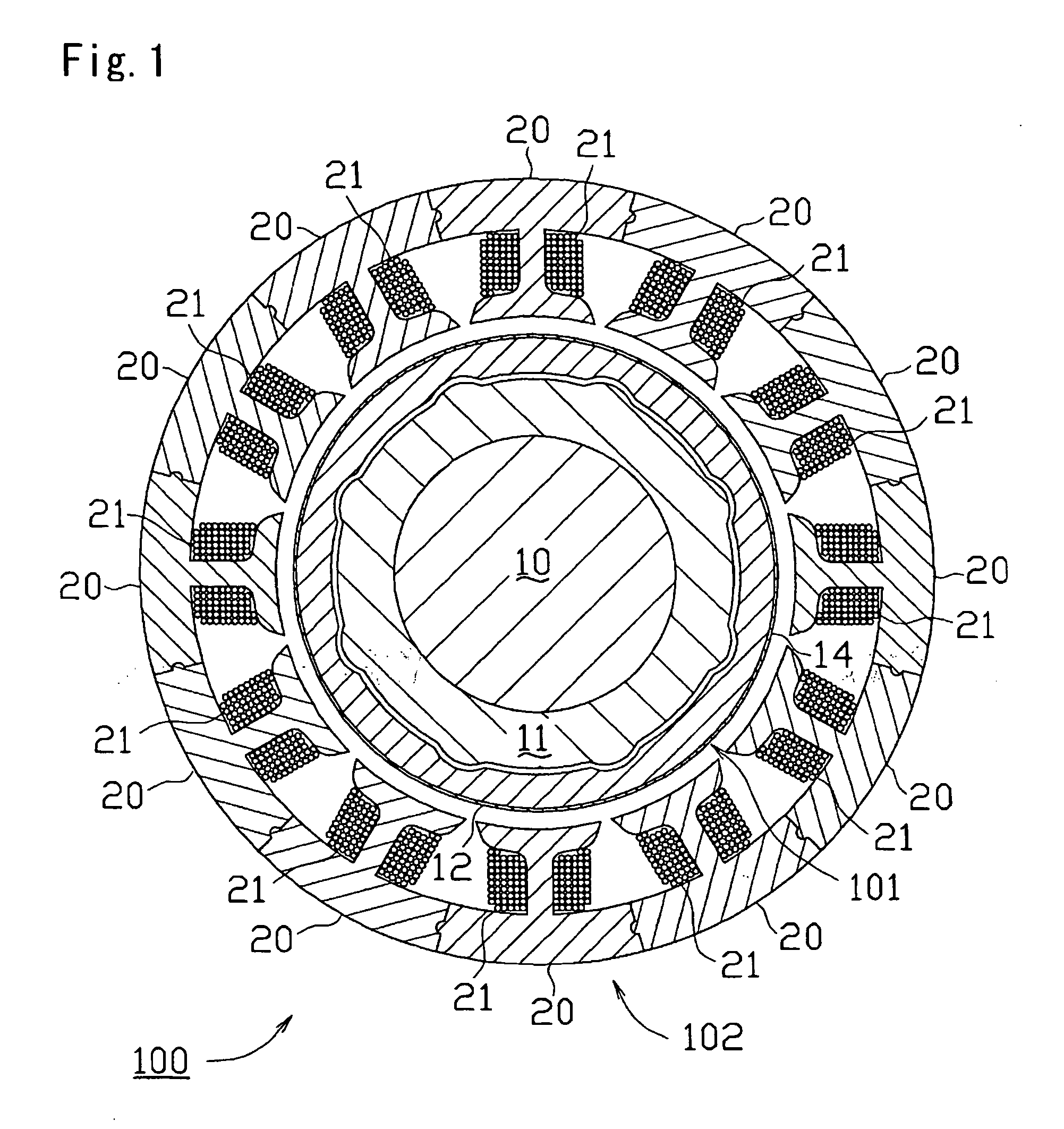
[0029] A brushless motor 100 in accordance with an embodiment of the present invention is of an inner rotor type structured by an inner rotor and an outer stator. As shown in FIG. 1, the inner rotor is constituted by a rotor (a rotor for a brushless motor) 101, and the outer stator is constituted by a stator 102 in which separated cores 20 separated every teeth are annularly connected by a predetermined number, twelve in this case, and a coil 21 is wound around each of the teeth. The rotor 101 is rotatably arranged by forming a fixed gap in the stator 102.

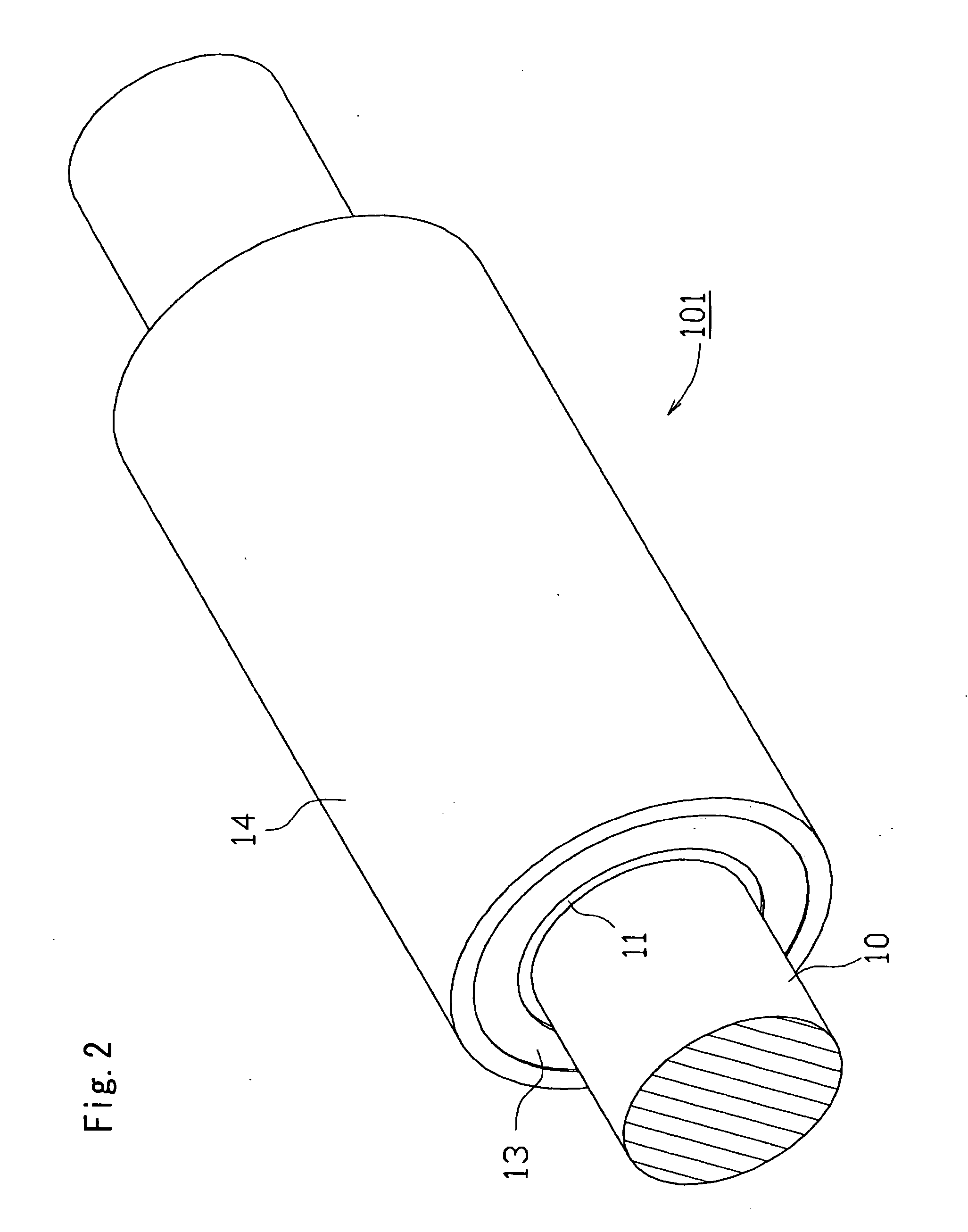
[0030] The rotor 101 is provided with a shaft 10 forming a shaft of the motor, a rotor yoke 11 concentrically provided in the shaft 10, a sintered ring magnet 12 provided in an outer periphery of the rotor yoke 11, a protecting plate 13 covering both end surfaces in an axial d...


PUM


Abstract

The invention provides a means which can securely prevent an idle running and a scattering of a magnet while restricting a manufacturing cost as low as possible, in a rotor used in a brushless motor. A rotor (101) is provided with a sintered ring magnet (12) in which not-ground recess portions (12a) are formed in an axial direction of a inner peripheral surface in correspondence to a magnetic pole, and a portion between the recess portions (12a) is ground in an inner peripheral surface (12b) having a desired inner diameter, a rotor yoke (11) in which convex portion (11b) having a larger diameter than the inner diameter (r4) of the sintered ring magnet (12) are formed in an axial direction of an outer peripheral surface in correspondence to the recess portion (12a), and a through hole (11a) is pierced in an axial center, and which is concentrically adhered to the sintered ring magnet (12) by fitting the recess portion (12a) and the convex portion (11b), and a shaft (10) inserted and fitted to the through hole (11a) of the rotor yoke (11).

Description

BACKGROUND OF THE INVENTION [0001] 1. Field of the Invention [0002] The present invention relates to a structure of a rotor for a brushless motor provided with a sintered ring magnet. [0003] 2. Description of the Related Art [0004] Various motors such as an induction motor, a commutator motor and the like have been conventionally used as a motor, however, a brushless motor having a high performance has been frequently used in recent years. In an inner rotor type brushless motor which is one of the brushless motor, a magnet is arranged in an outer periphery of a rotor forming an inner rotor and is fixed to a rotor yoke by an adhesive agent. The magnet includes a so-called segment type in which a plurality of magnet pieces are arranged in a peripheral direction in correspondence to a number of poles of the brushless motor, and a ring magnet which is formed in a cylindrical shape and is magnetized in multi poles in a peripheral direction. However, in the segment type, an adhesive stren...

Claims


Application Information

Patent Timeline
Patent Type & Authority Applications(United States)
IPC IPC(8): H02K29/00H02K1/27H02K7/00H02K21/14
CPCH02K1/2733
Inventor KINASHI, YOSHIKAZUNAKAO, MASATOSHI
Owner ICHINOMIYA ELECTRIC
Why Eureka
Try Eureka