Slotless rotary electric machine and manufacturing method of coils for such a machine

a rotary electric machine and manufacturing method technology, applied in the direction of magnets, magnetic circuit shapes/forms/construction, magnetic bodies, etc., can solve the problems of reducing the efficiency of the generator in a high speed range, circulating current loss, and increasing the loss of copper to a significant extent, so as to achieve compact and efficient effect and large outpu

a rotary electric machine and manufacturing method technology, applied in the direction of magnets, magnetic circuit shapes/forms/construction, magnetic bodies, etc., can solve the problems of reducing the efficiency of the generator in a high speed range, circulating current loss, and increasing the loss of copper to a significant extent, so as to achieve compact and efficient effect and large outpu

US20050225197A1Inactive Publication Date: 2005-10-13HONDA MOTOR CO LTD

Image

  • Slotless rotary electric machine and manufacturing method of coils for such a machine
  • Slotless rotary electric machine and manufacturing method of coils for such a machine
  • Slotless rotary electric machine and manufacturing method of coils for such a machine

Examples


Embodiment Construction

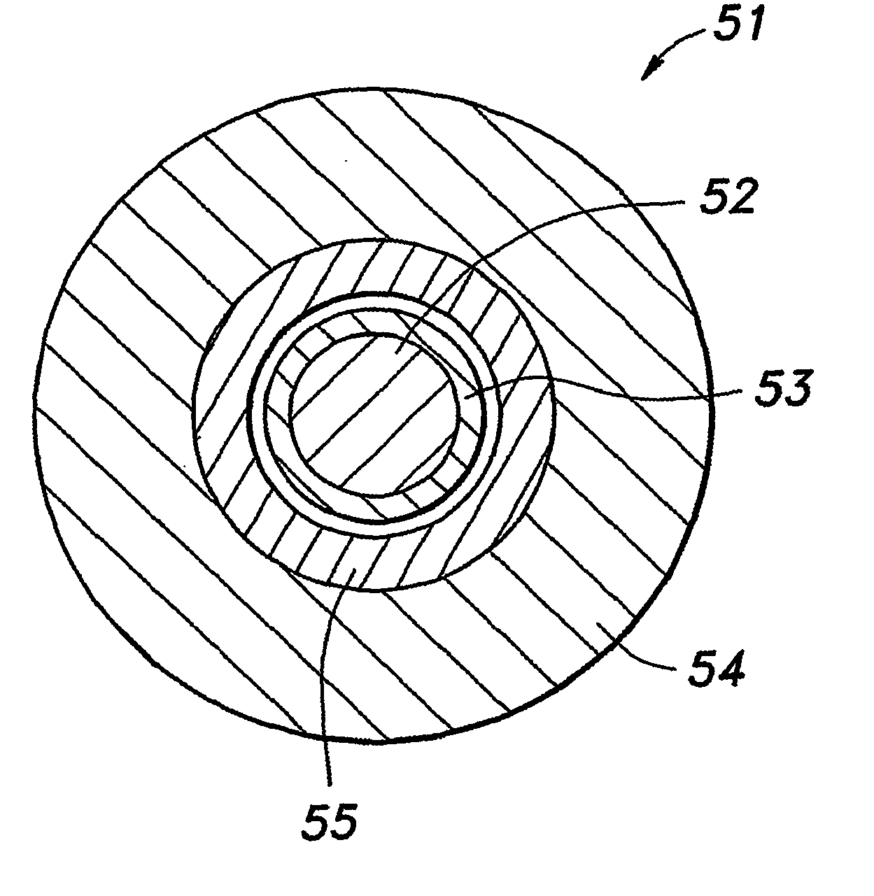
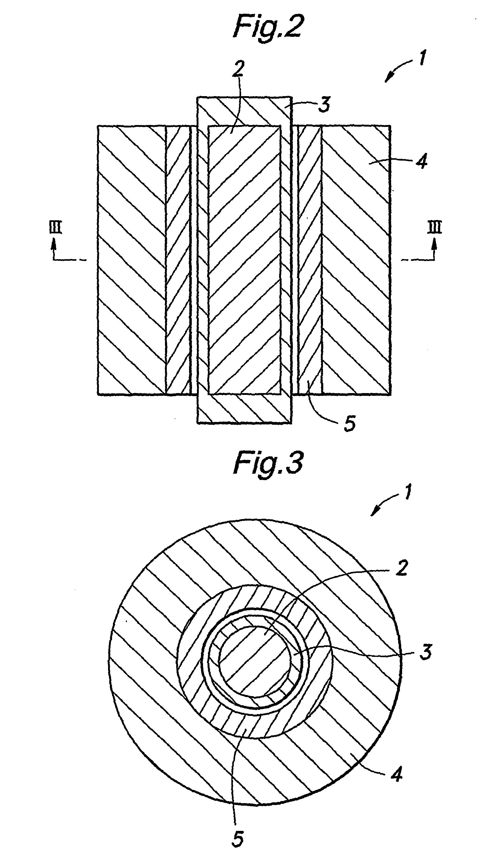
[0052]FIG. 6 is a sectional view similar to FIG. 3 showing a slotless permanent magnet generator embodying the present invention. Similarly as the conventional slotless permanent magnet generator 1 shown in FIGS. 3 to 5, this slotless permanent magnet generator 51 comprises a substantially cylindrical rotor 53 incorporated with a permanent magnet 52, a stator iron core 54 surrounding the rotor 53 and a coil 55 attached to the inner circumferential surface of the stator iron core 54 so as to define an air gap in relation with the outer circumferential surface of the rotor 53. However, the cross sectional shape of the conductor 60 forming the coil 55 is different from that of the conventional conductor.

[0053] Referring to FIG. 7a, the conductor 60 of the slotless permanent magnet generator 51 is provided with an elongated cross section or more particularly a flat rectangular cross section having a long side and a short side. For instance, the longs side of the conductor 60 shown in F...


PUM

PropertyMeasurementUnit
electric phase angleaaaaaaaaaa
diameteraaaaaaaaaa
diameteraaaaaaaaaa

Abstract

In a slotless permanent magnet rotary electric machinery, comprising a substantially cylindrical rotor (53) incorporated with a permanent magnet (52), a stator iron core (54) surrounding the rotor; and a coil (55) provided between the rotor (53) and stator core (54) in a spaced relationship with respect to the rotor (53), the coil (55) comprises a plurality of turns which are shifted from one turn to another along the circumferential direction in a mutually overlapping manner; and the coil turns are formed by a conductor (60, 60a, 60b) having an elongated cross section, a long axis of the cross section extending in a radial direction. This provides rotary electric machinery which can significantly reduce loss in a high speed range without substantially increasing copper loss.

Description

TECHNICAL FIELD [0001] The present invention relates to a slotless permanent magnet rotary electric machinery and a method of making coils for such machinery. BACKGROUND OF THE INVENTION [0002] Conventionally, rotary machinery in such forms as electric generators and electric motors is sometimes constructed as a slotless type having no slot for receiving coils to the end of reducing torque ripples (or cogging torque). See Japanese patent laid open publication No. 2002-272049A, for instance. In the slotless motor described in this prior patent publication, a flat conductor having a rectangular cross section is used instead of a more common conductor having a circular cross section to the end of maximizing the space factor. The flat wire is wound in a spiral path from the inner circumference to the outer circumference. On the other hand, Japanese patent laid open publication No. 2002-247791A discloses a coil winding method which is suitable for winding hexagonal coils for slotless mot...

Claims


Application Information

Patent Timeline
13 Oct 2005
Publication
US20050225197A1
IPC
H02K1/12; H02K3/04; H02K3/47; H02K15/04; H02K21/12
CPC
H02K3/47; H02K15/0471; Y10T29/49071; Y10T29/49009; H01F41/061
Inventors
NAGANO, MASAO; OZAWA, MASARU