Piezoelectric actuator and fluid ejection head having the same

a technology of fluid ejection head and actuator, which is applied in the direction of machines/engines, positive displacement liquid engines, inking apparatus, etc., can solve the problems of insufficient manufacturing efficiency, increase in the volumetric change in the pressure chamber, and inability to acquire a characteristic which can respond to a recent high level of demand, etc., to enhance the deformation efficiency enhance reliability, and enhance the stability of the deformation of the piezoelectric elemen

Active Publication Date: 2005-10-13
SEIKO EPSON CORP
View PDF4 Cites 7 Cited by
  • Summary
  • Abstract
  • Description
  • Claims
  • Application Information

AI Technical Summary

Benefits of technology

[0008] It is therefore an object of the invention is to enhance stability of deformation of a piezoelectric element of multilayer structure, as well as to enhance

Problems solved by technology

Further, an increase in the amount of deformation of the piezoelectric element leads to an increase in the amount of volumetric change in the pressure chamber.
However, acquisition of a characteristic which can respond to a recent high level of demand cannot be achieved by mere use of the piezoelectric element o

Method used


Image

  • Piezoelectric actuator and fluid ejection head having the same
  • Piezoelectric actuator and fluid ejection head having the same
  • Piezoelectric actuator and fluid ejection head having the same

Examples


second embodiment

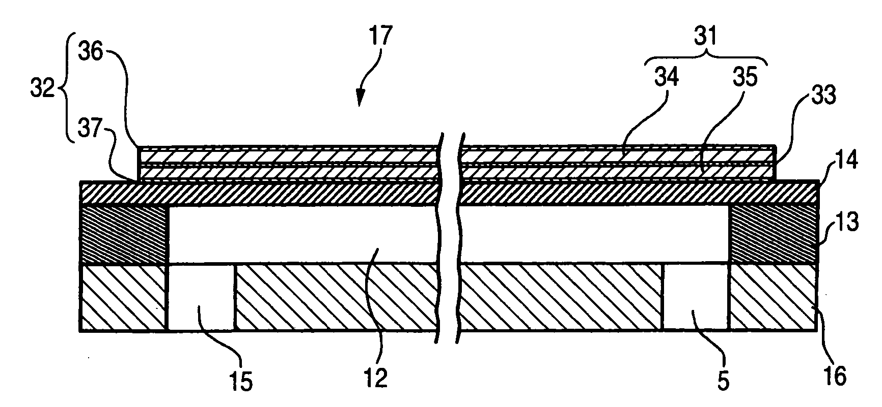
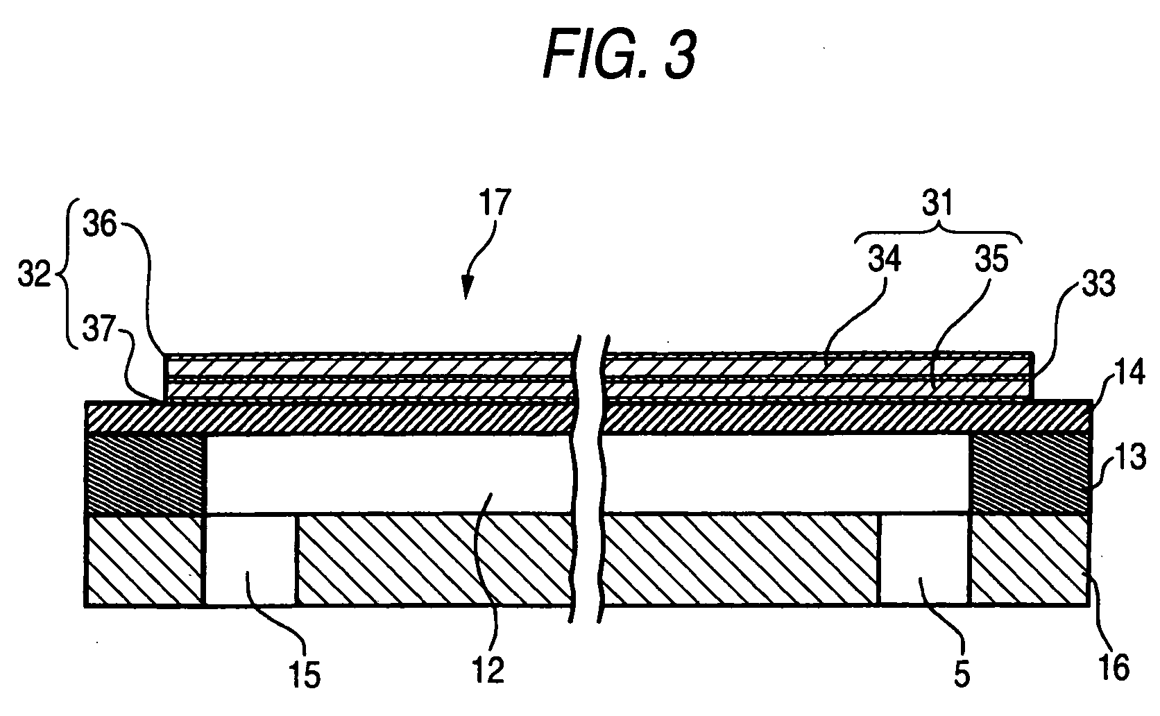
[0075] A second embodiment shown in FIG. 6 is characterized in that the upper piezoelectric body 34 is formed so as to become wider than the inner dimension wc of the pressure chamber 12; that the upper common electrode 36 is formed so as to become wider than the lower common electrode 37; and that the upper common electrode 36 is formed over the entire width of the upper piezoelectric body 34 in a continuous manner.

[0076] In the embodiment, the width wp1 of the upper piezoelectric body 34 is formed so as to become wider than the inner dimension wc of the pressure chamber 12 and the width wp2 of the lower piezoelectric body 35 and narrower than an interval wc″ (an interval wc″ between partitions) between the centers of pressure chamber partitions 38 in a widthwise direction. Further, the center of the upper piezoelectric body 34 in the transverse direction is aligned with the center of the pressure chamber 12 in the transverse direction. In other words, the upper piezoelectric body ...

third embodiment

[0086] A third embodiment shown in FIG. 7 is characterized in that the lower piezoelectric body 34 is formed so as to become wider than the inner dimension wc of the pressure chamber 12.

[0087] In the embodiment, the width wp2 of the lower piezoelectric body 35 is formed so as to become wider than the inner dimension wc of the pressure chamber 12. The individual sections are provided in descending order from the widest section as follows. Specifically, the partition interval wc″ is the widest, and the width wp1 of the upper piezoelectric body 34 and the width we1 of the upper common electrode 36 are the second widest. The width wp2 of the lower piezoelectric body 35 and the width we2 of the drive electrode 33 are the third widest. The inner dimension wc of the pressure chamber 12 is the fourth widest. The width we3 of the lower common electrode 37 is the smallest.

[0088] Even in the embodiment, the centers of the individual sections in the transverse direction thereof are aligned wit...


PUM


Abstract

A first common electrode is formed on a vibration plate and to be fixed at a predetermined potential. A first piezoelectric layer is laminated on the first common electrode and having a first thickness. A drive electrode is laminated on the first piezoelectric layer, to which a drive signal is supplied externally. A second piezoelectric layer is laminated on the drive electrode and having a second thickness thicker than the first thickness. A second common electrode is laminated on the second piezoelectric layer and to be fixed at the predetermined potential.

Description

TECHNICAL FIELD [0001] The present invention relates to a piezoelectric actuator having a piezoelectric element, the element serving as a drive source, formed on the surface of a diaphragm. The present invention also relates to a liquid ejection head incorporating such a piezoelectric element provided on the surface of the diaphragm opposite a pressure chamber and changes the volume of the pressure chamber by the piezoelectric element. BACKGROUND ART [0002] A piezoelectric element becomes deformed upon receipt of supplied electric energy and is widely used as, e.g., a liquid ejection head, a micropump, or a drive element for use with a sound-generating member (a speaker or the like). Here, the liquid ejection head ejects droplets from nozzle orifices by inducing pressure fluctuations in liquid stored in a pressure chamber. For instance, the liquid ejection head includes a recording head used in an image recording apparatus such as a printer, a liquid-crystal ejection head used in ma...

Claims


Application Information

Patent Timeline
IPC IPC(8): B41J2/055B41J2/045B41J2/14B41J2/16F04B43/04H01L41/083H01L41/09
CPCB41J2/14233B41J2/161B41J2/1623B41J2/1632B41J2002/14258B41J2002/14491B41J2202/11H01L41/0973H10N30/2047
Inventor CHANG, JUNHUAKATAKURA, TAKAHIRO
Owner SEIKO EPSON CORP
Why Eureka
Try Eureka