Impulse generation circuit

a technology of impulse generation and circuit, which is applied in the field of impulse generation circuit, can solve the problems of system performance degrading, difficult adjustment of pulse waveform and pulse width, etc., and achieve the effects of preventing ringing, minimizing termination impedance variation, and easy adjustment of pulse width

Inactive Publication Date: 2005-10-13
SAMSUNG ELECTRONICS CO LTD
View PDF3 Cites 7 Cited by
  • Summary
  • Abstract
  • Description
  • Claims
  • Application Information

AI Technical Summary

Benefits of technology

[0019] It is another aspect of the present invention to provide an impulse generation circuit that prevents a ringing phenomenon by preventing a reflected signal from being re-reflected using a resistor at an end of a drive terminal.
[0020] It is another aspect of the present invention to provide an impulse generation circuit that minimizes the termination impedance variation by making use of a drain terminal and a collector terminal of a transistor as output terminals.
[0021] It is yet another aspect of the present invention to provide an impulse generation circuit that can easily adjust a pulse width according to the length of an external transmission line and can be easily implemented in an integrated structure.

Problems solved by technology

The adjustment of a pulse waveform and a pulse width is not easy in the conventional impulse generation circuits using the above-described methods.
When the conventional impulse generation circuits are used, system performance may be degraded due to device characteristic variations, temperature variations, etc.

Method used


Image

  • Impulse generation circuit
  • Impulse generation circuit
  • Impulse generation circuit

Examples


Embodiment Construction

[0034] Preferred embodiments of the present invention will be described in detail herein below with reference to the accompanying drawings. Although the present invention will be described with respect to representative embodiments, other embodiments and variations are within the scope of the present invention.

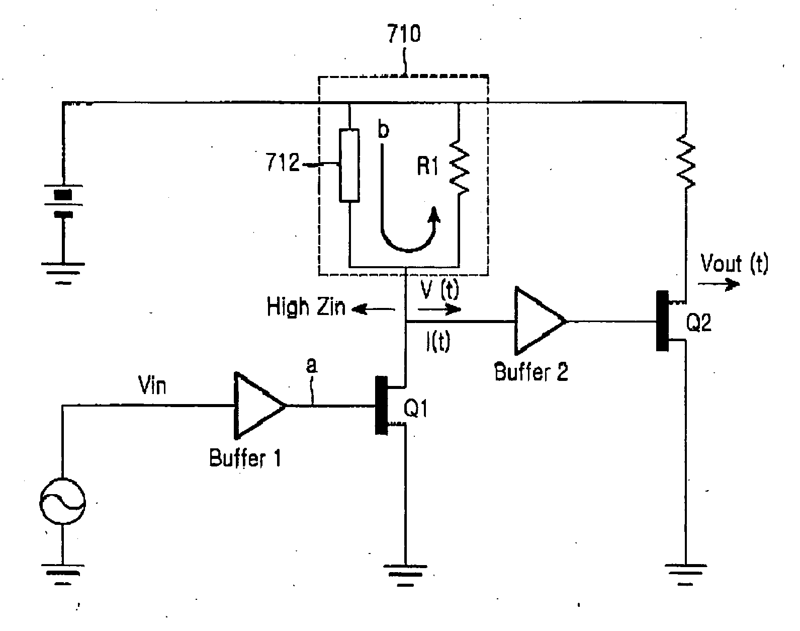
[0035] An embodiment of the present invention to be described below generates an impulse having a width corresponding to a predetermined time by causing an input signal and a reflected signal to cancel each other out. The reflected signal has a polarity opposite to that of the input signal when the predetermined time has elapsed. For this purpose, the embodiment of the present invention includes a reflection delay device for generating the reflected signal in which the polarity of the input signal is inverted when the predetermined time (reflection time) has elapsed after a signal input. The reflection delay device can be implemented using a transmission line. One end of the ...


PUM


Abstract

An impulse generation circuit is provided for generating an impulse using a transmission line. Impulse characteristics of the impulse generation circuit are varied with the length of a transmission line rather than the characteristic variation of various devices used therein. The length of the transmission line is adjusted, such that a width of a generated pulse is adjusted. Because an end of the transmission line is short-circuited, the transmission line length can be easily adjusted on a substrate, and a ringing phenomenon due to re-reflection can be removed using termination impedance.

Description

PRIORITY [0001] This application claims priority to an application entitled “IMPULSE GENERATION CIRCUIT”, filed in the Korean Intellectual Property Office on Mar. 17, 2004 and assigned Serial No. 2004-17988, the contents of which are incorporated herein by reference. BACKGROUND OF THE INVENTION [0002] 1. Field of the Invention [0003] The present invention relates generally to an impulse generation circuit, and more particularly to an impulse generation circuit using a transmission line. [0004] 2. Description of the Related Art [0005] Conventionally, and as used herein, the term “impulse” refers to any short-duration voltage, current, or wave signal that is used to generate a large amplitude. A periodic impulse signal is referred to as a pulse. However, the term “pulse” is a generic term that includes an impulse and a pulse. [0006] Such a pulse includes a clock pulse and a frame pulse, and is used in a bit synchronization system and a frame synchronization system. More specifically, ...

Claims


Application Information

Patent Timeline
Patent Type & Authority Applications(United States)
IPC IPC(8): H03K3/017A61N1/18H03K5/06
CPCH03K5/06H03K3/017
Inventor KIM, YOUNG-HWANLEE, SEONG-SOOKIM, HAK-SUNLEE, CHANG-SEOKPARK, SOO-YONGKIM, YU-SIN
Owner SAMSUNG ELECTRONICS CO LTD
Why Eureka
Try Eureka