Electromagnetic coil assembly

a technology of electromagnetic coils and components, applied in the direction of magnets, transformers/inductance coils/windings/connections, magnetic bodies, etc., can solve the problems of increasing the complexity of the assembly, labor-intensive and costly manufacturing of electromagnetic coils,

Inactive Publication Date: 2005-10-13
POLYMER TECH CORP
View PDF26 Cites 35 Cited by
  • Summary
  • Abstract
  • Description
  • Claims
  • Application Information

AI Technical Summary

Benefits of technology

[0005] In a first aspect, the present invention is directed to a housing assembly for use in an electromagnetic coil assembly with a coil of magnet wire, first and second connectors and first and second lead wire ends, wherein the magnet wire has first and second ends, wherein each connector retains and electrically connects one end of the magnet wire and one lead wire end. The housing assembly includes a bobbin, a cover piece and a connector housing. The bobbin includes a hub, a first flange and a second flange. The hub has a longitudinal axis. The first and second flanges are spaced axially from each other. The hub and flanges together define a circumferential bobbin channel for receiving the coil of magnet wire. The bobbin is made from a material that is an electrical insulator. The cover piece is self-supporting and extends circumferentially around the coil of magnet wire. The connector housing is connected to the cover piece. The connector housing has at least one connector housing channel sized to hold the first and second connectors. The at least one connector housing channel has first and second end walls which prevent withdrawal of the first and second connectors from the connector housing.

Problems solved by technology

Some electromagnetic coil assemblies can be labour intensive and costly to manufacture.
Additionally, some assemblies incorporate many components thus increasing their complexity.

Method used


Image

  • Electromagnetic coil assembly
  • Electromagnetic coil assembly
  • Electromagnetic coil assembly

Examples


Embodiment Construction

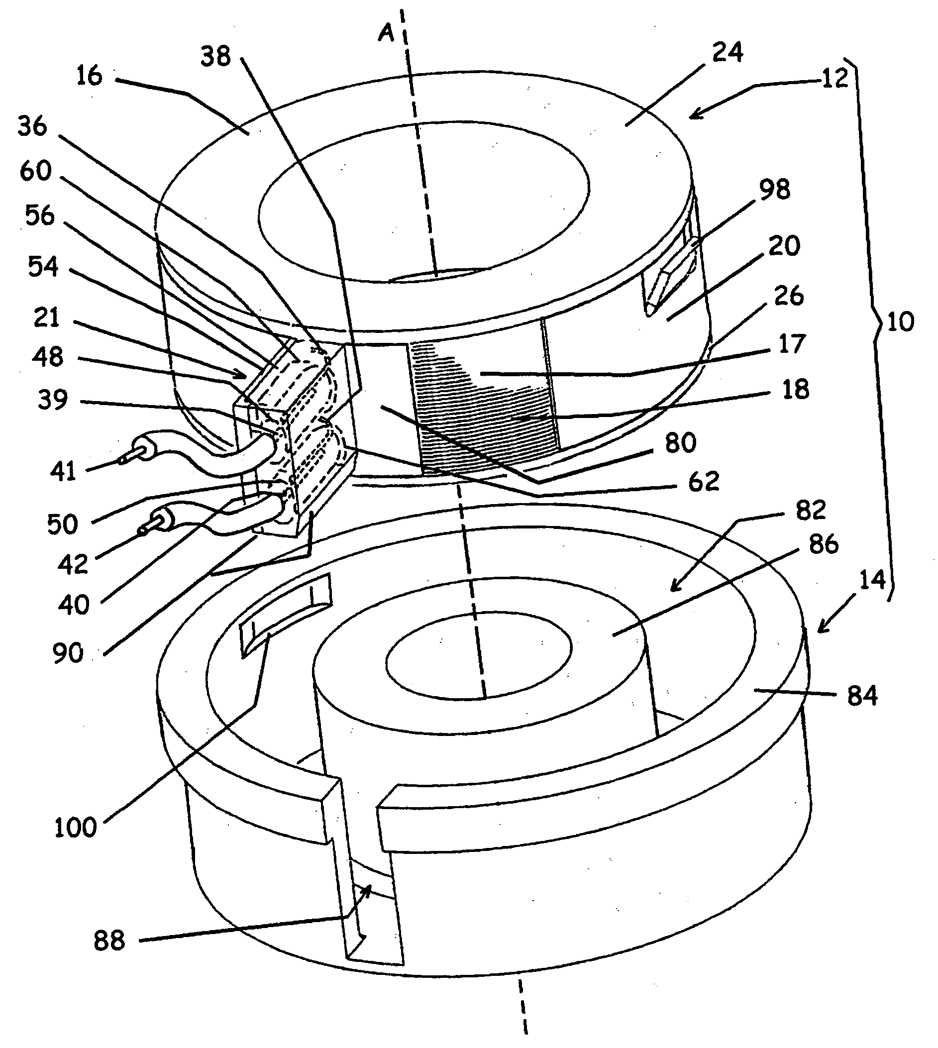
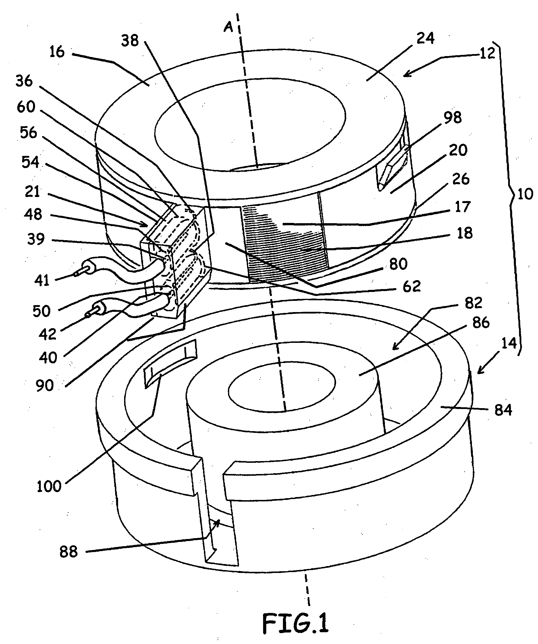
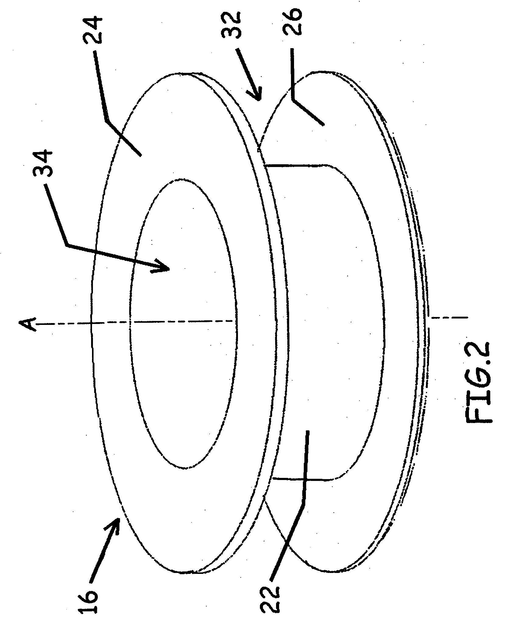
[0019] Reference is made to FIG. 1, which shows a partially exploded view of an electromagnetic coil assembly 10 in accordance with a first embodiment of the present invention. The electromagnetic coil assembly 10 includes a subassembly 12 and a yoke 14. The subassembly 12 includes a bobbin 16, a coil 17 of magnet wire 18, a cover piece 20 and a connector housing 21. Referring to FIG. 2, the bobbin 16 includes a hub 22, a first flange 24 and a second flange 26. The bobbin 16 has a longitudinal axis A.

[0020] The hub 22 may have any suitable shape. For example it may have a generally cylindrical shape about the axis A. The first and second flanges 24 and 26 are positioned at the axial ends of the hub 22 and are thus spaced axially from each other. The first and second flanges 24 and 26 may be circular, as shown in the figures, or alternatively, they may have some other shape, such as a square shape.

[0021] The first and second flanges 24 and 26 may be circular, as shown in the figure...


PUM

PropertyMeasurementUnit
compressive forceaaaaaaaaaa
resilientaaaaaaaaaa
electrically insulativeaaaaaaaaaa

Abstract

An electromagnetic coil assembly is provided. The electromagnetic coil assembly includes a bobbin, a coil of magnet wire and a cover piece. The bobbin includes a hub, a first flange and a second flange. The hub has a longitudinal axis. The first and second flanges are spaced axially from each other. The hub and flanges together define a circumferential bobbin channel. The bobbin is made from a material that is an electrical insulator. The coil of magnet wire is positioned around the hub in the circumferential bobbin channel. The magnet wire has first and second ends. The cover piece is self-supporting and is sized to extend circumferentially around the coil of magnet wire. The cover piece is resilient and exerts a compressive force radially inwardly on the coil of magnet wire.

Description

FIELD OF THE INVENTION [0001] This invention relates to an electromagnetic coil assembly. BACKGROUND OF THE INVENTION [0002] An electromagnetic coil assembly is typically made by winding a large number of turns of magnet wire around a bobbin, thereby forming a coil around the bobbin. The bobbin is typically made from non-conductive and non-magnetic material. The coil is connected to an electrical power source via electrical lead wires or terminals. With a voltage across the ends of the magnet wire, an electrical current will circulate through the coil, which in turn will generate a toroidal magnetic flux that envelopes the coil. Soft iron or other ferromagnetic material is normally used to make a yoke that envelops the coil. The yoke provides a magnetic circuit path to concentrate the magnetic flux. [0003] Such electromagnetic coil assemblies have found many applications in components used in the manufacture of vehicles, such as, for examples electromagnetic-actuated clutches. Other...

Claims


Application Information

Patent Timeline
Patent Type & Authority Applications(United States)
IPC IPC(8): H01F5/00H01F5/04H01F7/06H01F7/123H01F7/127H01F27/02H01F27/04
CPCH01F5/04H01F7/06H01F7/123H01F7/127H01F27/04H01F2007/062
Inventor TRAN-NGOC, TRUCBENNETT, CHRISTOPHER
Owner POLYMER TECH CORP
Why Eureka
Try Eureka