Whip antenna high voltage protection device with an integrated electric charge bleed-off system

a protection device and high-voltage protection technology, applied in the direction of resonant antennas, coupling device connections, elongated active elements, etc., can solve the problems of radio equipment damage, harmful electric shock, and the inability to integrate an unintended electric charge dissipation methodology

Active Publication Date: 2005-10-13
SHAKESPEARE CO
View PDF3 Cites 6 Cited by
  • Summary
  • Abstract
  • Description
  • Claims
  • Application Information

AI Technical Summary

Problems solved by technology

For example, the patents to Pokryvailo et al., U.S. Pat. No. 6,366,251, and Goodall et al., U.S. Pat. No. 4,513,338 describe methods of high voltage protection, but they do not integrate an unintended electric charge dissipation methodology.
Ironically, both of the above patents disclose an antenna that can create a condition of a dangerous static charge build up that can result in harmful electric shock if a human body acts as a discharge path for the accumulated charge.
Radio equipment may be damaged by this unintended accumulated electric discharge event.
It is speculated that a plasma field condition originating from the storm cloud system, propagates electric plasma through the dry desert air that results in a substantial charge build-up in the antenna system that is employing a “high-voltage protection device / capacitor.” This charge build-up continues until a resulting uncontrolled electric discharge event manifests itself.
This charge effect has resulted in “gun shot” like sounding discharge events that can be very disconcerting in a desert military theater of operations as well as causing damage to communications equipments.
It is acknowledged that subjecting any high voltage rated capacitor to 24 KV will cause it to heat up due to inherent losses.
The '251 patent asserts that Goodall et al, U.S. Pat. No. 4,513,338, is flawed because a capacitor using a Teflon™ dielectric is “linear” and therefore cannot possibly be designed to limit low frequency current to below 5 milliamperes while passing an “unobstructed” high frequency current.
Also, since the capacitance has decreased, one may point out that the high frequency capacitance reactance of the non-linear capacitor may “interfere” more with high frequency whip antenna operations than the linear capacitor once heated up by a high voltage contact event.
The bad thing is that the Xc value is also greater at the radio frequency operation of the whip antenna, and could impede its normal operation until “cooled” off.

Method used


Image

  • Whip antenna high voltage protection device with an integrated electric charge bleed-off system
  • Whip antenna high voltage protection device with an integrated electric charge bleed-off system
  • Whip antenna high voltage protection device with an integrated electric charge bleed-off system

Examples


Embodiment Construction

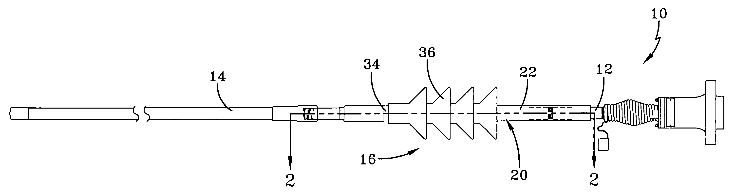
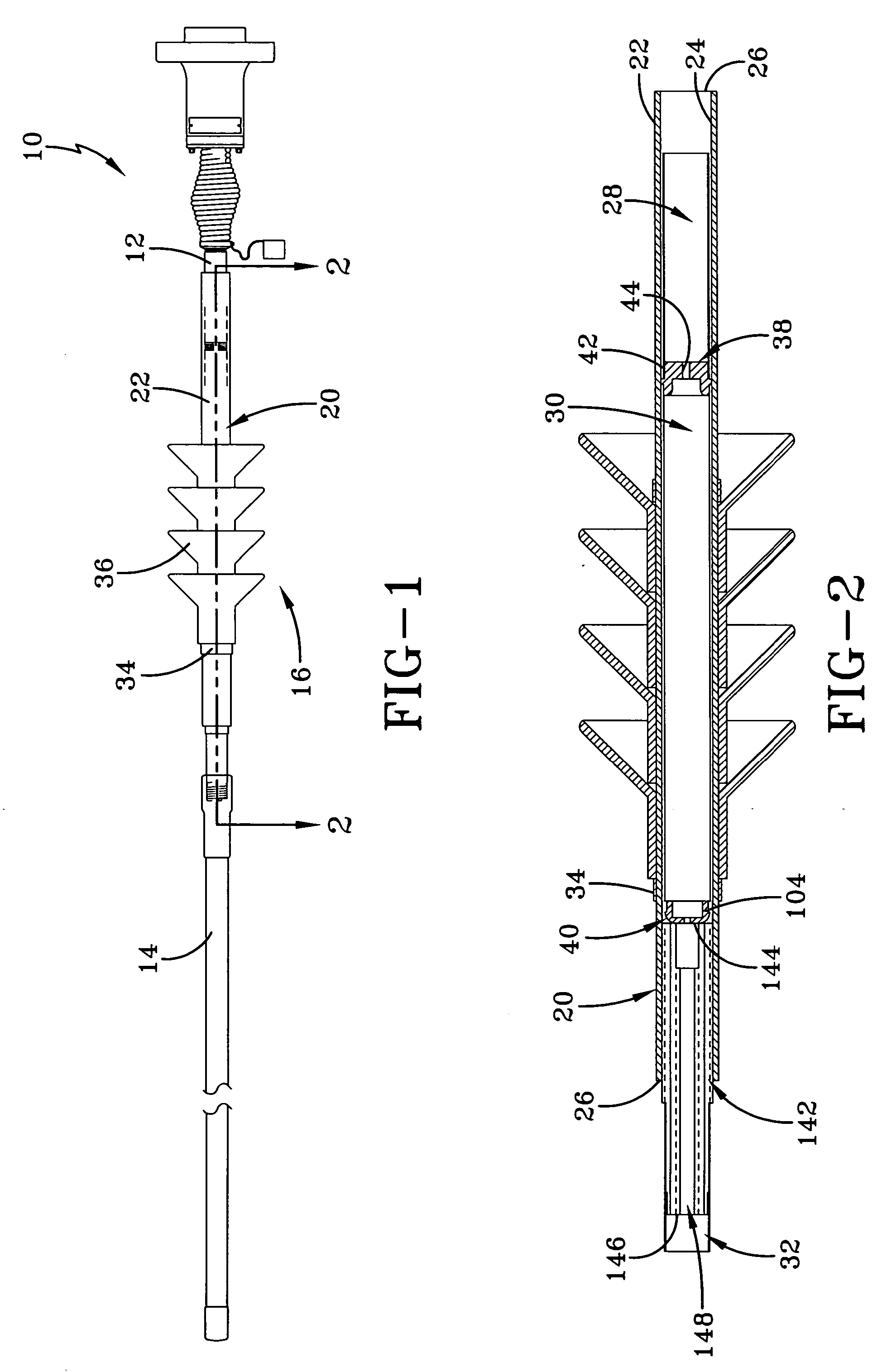
[0020] Referring now to the drawings and in particular to FIGS. 1 and 2 it can be seen that a whip antenna made in accordance with the concepts of the present invention is designated generally by the numeral 10. The antenna 10 is typically provided in multiple sections. The antenna includes a proximal conductor element 12 which is associated with the base of the antenna or in close proximity thereto and that is connectable to a distal conductor element 14 which is associated with the tip of the antenna. An antenna protection device, designated generally by the numeral 16, is interposed between the elements 12 and 14 for the purpose of protecting the overall operation of the antenna as will become apparent from the detailed description. It will be appreciated that the protection device 16 could be integrally incorporated into the antenna or provided between the elements. The protection device 16 is envisioned to be used in mobile military antenna applications, although it will be app...


PUM


Abstract

An antenna protection device includes a pair of opposed contacts, an inner electrode connected to one of the contacts. The outer electrode is separated from the inner electrode by a dielectric layer and connected to the other of the contacts. A bleed-off resistor is connected between the opposed contacts to dissipate any accumulated. Corona rings may be employed around the foregoing components to improve operation of the device.

Description

TECHNICAL FIELD [0001] This invention relates to antenna systems. More particularly, the present invention relates to an antenna component that provides high voltage protection and dissipation of excessive electric charge. BACKGROUND ART [0002] It is known in the prior art to integrate a protective capacitor to act as a high-pass filter within an antenna. Such a protective element allows the radio frequency function of a whip antenna while providing substantial series impedance in the event of unintended contact with over-head high-voltage electric lines that a vehicle employing a large whip antenna may encounter. For example, the patents to Pokryvailo et al., U.S. Pat. No. 6,366,251, and Goodall et al., U.S. Pat. No. 4,513,338 describe methods of high voltage protection, but they do not integrate an unintended electric charge dissipation methodology. Ironically, both of the above patents disclose an antenna that can create a condition of a dangerous static charge build up that can ...

Claims


Application Information

Patent Timeline
Patent Type & Authority Applications(United States)
IPC IPC(8): H01Q1/50H01Q9/30
CPCH01Q1/36H01Q1/50H01Q9/30H01R24/48H01R2103/00
Inventor MARTEK, GARY A.LEWIS, JOHN R. JR.
Owner SHAKESPEARE CO
Why Eureka
Try Eureka