Rubber kneading machine

Inactive Publication Date: 2005-10-13
SUZUKA ENG
View PDF2 Cites 18 Cited by
  • Summary
  • Abstract
  • Description
  • Claims
  • Application Information

AI Technical Summary

Benefits of technology

[0028] The rubber kneading machine constructed as described above allows the rolls and the distal end of the extrusion cylinder to be cleaned easily and securely by moving the roll supporting frames and the extrusion cylinder away from each other, or allows the interior of the extrusion cylinder and the screws to be cleaned easily and securely by moving the extrusion cylinder and the screw extruder main body away from each other to expose the screws when, for example, changing the color or composition of a rubber dough, while maintaining high safety for an operator by its high level of closure.
[0029] The rubber kneading machine in accordance with the present invention described in detail above is intrinsically safe, because the rubber sheet outlet side of the rolls (the side where rolls 1 and 2 mesh each other and do not rotate) is the operating side, which is different from a conventional roll rubber kneading machine. Moreover, the rubber circulating mechanism that includes the carrying means for sending a rubber sheet sent out from between the upper and lower rolls to the hopper of the screw extruder is provided, so that an operator does not have to touch rubber on a rotating roll surface in performing a rubber kneading operation. Depending on the type of rubber, completely unattended operation is possible.
[0030] The kneading effect in the rubber kneading machine according to the present invention is marked particularly when the rotational speeds of the upper and lower rolls are differentiated. This arrangement applies high shearing to rubber passing thro

Problems solved by technology

This is because merely applying the shearing force to the rubber wound on the rolls results in uneven kneading action in the batch.
For an operator, however, it is unsafe to work on rubber, which unavoidably includes contact with rotating rolls.
The operation involves great danger, frequently causing serious injuries of operators by getting their hands or fingers caught between the rolls.
It has been ascertained that effect of finish kneading or mixing a vulcanizing agent cannot be obtained even when a circulation belt conveyor is provided to perform circulation kneading.
This operation is not only painstaking but extremely dangerous.
No equipment capable of performing such

Method used


Image

  • Rubber kneading machine
  • Rubber kneading machine
  • Rubber kneading machine

Examples


example

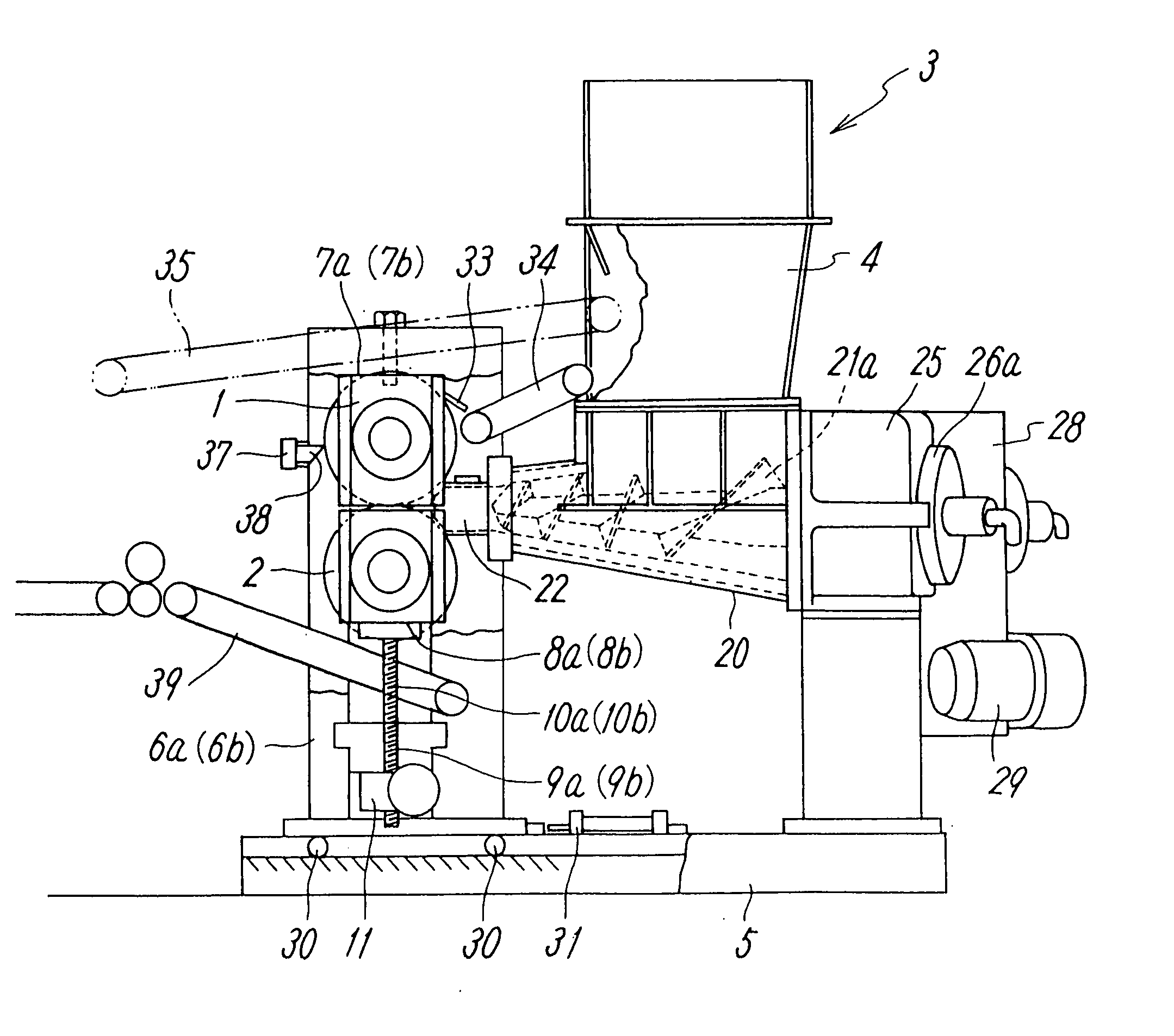
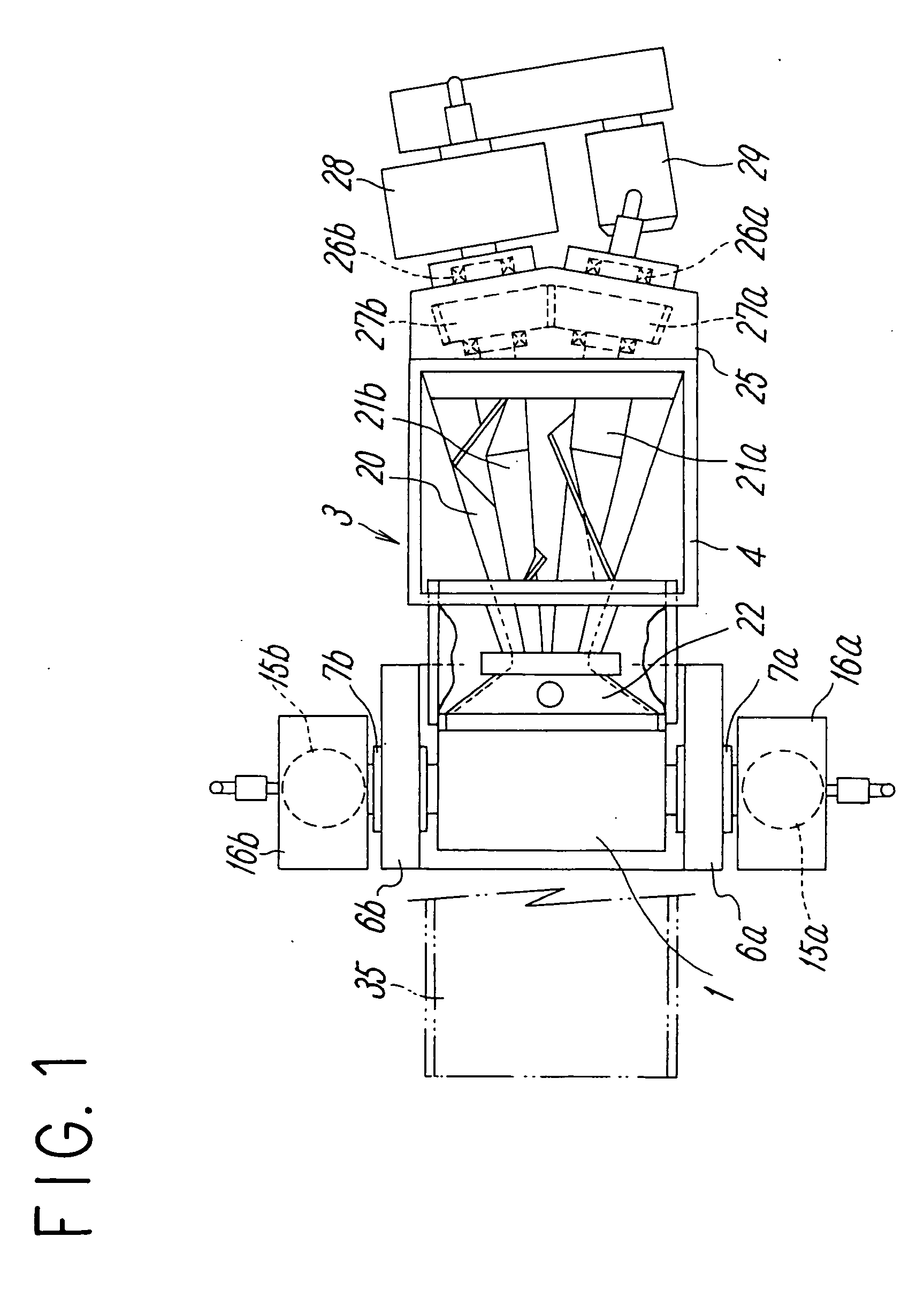
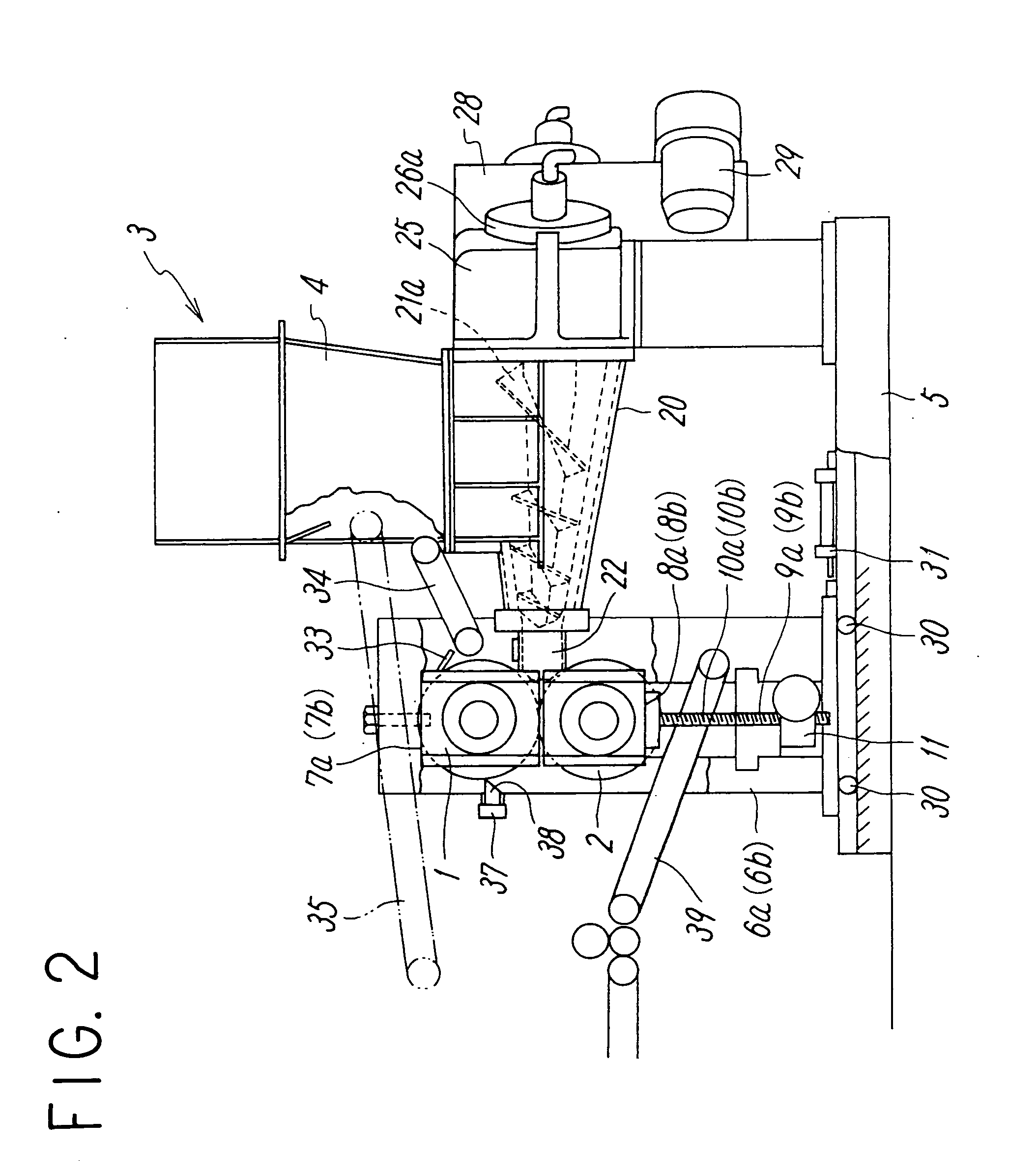
[0085] A rubber lump mixed and kneaded under a predetermined condition by a closed kneading machine (pressure kneader) was fed into the hopper 4 of the rubber kneading machine according to the first embodiment described above, and processed under the same conditions as those of a conventional roll machine. Depending on the type of rubber, the upper roll was set to be faster than the lower roll, so that the rubber wound on the upper roll, and was easily transferred by the scraper onto the belt conveyor, and then circulated to the hopper 4. The temperature of the rubber to be kneaded was set to 100° C., which is the same as that in the conventional roll kneading machine. The rubber was rolled into a sheet and taken out, and then sent out to a cooling apparatus. In about one minute after circulation was started, a powdered vulcanizing agent was added to the rubber in the hopper by hand, and the rubber was circulated for two minutes at 20 rpm, the rotational ratio of the upper and lower...


PUM

PropertyMeasurementUnit
Angleaaaaaaaaaa
Speedaaaaaaaaaa
Areaaaaaaaaaaa

Abstract

A rubber kneading machine obviates an operator having to touch rubber on a rotating roll surface to perform a rubber kneading operation, permits unattended operation, is intrinsically safe, improves a rubber kneading process productivity, secures stable quality of kneaded rubber, and allows a closed rubber supplying mechanism to be easily opened and exposed for easy cleaning. The rubber kneading machine includes two horizontal rolls closely disposed vertically, decelerators and variable speed motors rotating the rolls at different speeds, and a screw extruder supplying a rubber lump fed into a hopper at a proximal end to the rolls. A rubber circulating mechanism constructed mainly of a scraper and a belt conveyor, or a belt conveyor above the upper roll, feeds a rubber sheet, which has left the rolls, to the hopper. A mechanism releasing the screw extruder makes it possible to open and expose closed portions to facilitate cleaning.

Description

TECHNICAL FIELD [0001] Batch rubber kneading machines come in open type and closed type. The present invention relates to an open type rubber kneading machine adapted to perform finish kneading on rubber blocks kneaded by a closed type rubber kneading machine or to knead with an added vulcanizing agent and roll. BACKGROUND ART [0002] A conventionally known open type rubber kneading machine is generally a twin-roll machine. The twin-roll machine is disposed such that two roll shafts are parallel in a horizontal-plane and their rolling surfaces are close to each other. Raw material rubber is fed between rolls from above while rotatively driving the two rolls. The two rolls are rotated at different speeds while being pressed into contact so as to apply shearing action to the rubber, thereby imparting plasticizing and grinding effect. An operator manually cuts apart the rubber wound around the rolls on the operating side by a cutter and winds it up or moves it to one side of the rolls b...

Claims


Application Information

Patent Timeline
IPC IPC(8): B29B7/02B01F7/08B01F15/00B29B7/18B29B7/24B29B7/56B29C48/07B29C48/08B29C48/35B29C48/355B29C48/38B29C48/395B29C48/465B29C48/525B29C69/00B29K21/00
CPCB01F7/085B29C2793/009B29B7/18B29B7/24B29B7/566B29C47/0019B29C47/0059B29C47/0066B29C47/0801B29C47/32B29C47/34B29C47/38B29C47/402B29C47/50B29C47/522B29C47/60B29C47/6012B01F15/00922B29B7/7495B29C48/07B29C48/0019B29C48/0022B29C48/252B29C48/35B29C48/355B29C48/395B29C48/402B29C48/38B29C48/465B29B7/802B29B7/728B29B7/484B29B7/488B29B7/489B29B7/52B29C48/525B29C48/08B29B7/60B01F27/723B01F35/10B29B7/02B29B7/20B29B7/26
Inventor YADA, YASUOYADA, TATSUO
Owner SUZUKA ENG
Why Eureka
Try Eureka