Variable phase drive mechanism

a drive mechanism and variable phase technology, applied in the direction of valve drives, non-mechanical valves, positive displacement liquid engines, etc., can solve the problems of increasing the risk of one of the pistons being seized within the bore, reducing the component count and hence the manufacturing cost, and reducing the risk of the piston

Inactive Publication Date: 2005-10-13
MECHADYNE LTD
View PDF4 Cites 62 Cited by
  • Summary
  • Abstract
  • Description
  • Claims
  • Application Information

AI Technical Summary

Benefits of technology

[0013] While it is possible for the two pistons to be totally separate from one another, this places restrictions on the axial depth of the pistons and increases the risk of one of the pistons becoming seized within the bore.
[0014] In an embodiment of the invention designed to reduce the risk of...

Problems solved by technology

Furthermore, mounting of two locking pins coaxially reduces the component count and hence the manufacturing cost.
While it is possible for the two pistons to be to...

Method used


Image

  • Variable phase drive mechanism
  • Variable phase drive mechanism
  • Variable phase drive mechanism

Examples


Embodiment Construction

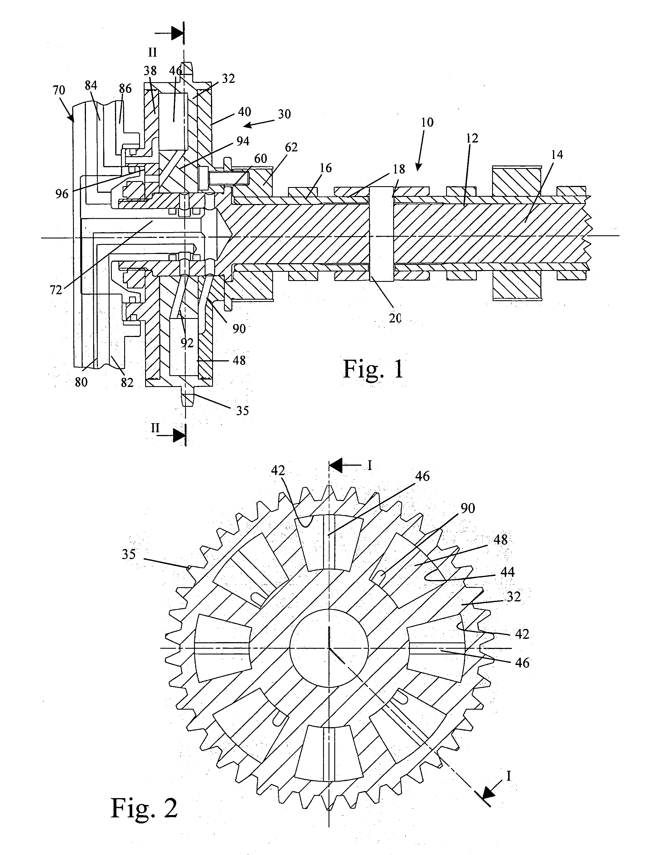
[0029]FIG. 1 shows a section through an assembled camshaft 10 with a twin vane-type phaser incorporated into its drive sprocket 30. The camshaft assembly comprises an inner shaft 14 surrounded by an outer sleeve or tube 12 which can rotate relative to the shaft 14 through a limited angle. One set of cams 16 is directly connected to the outer tube 12. A second set of cams 18 is freely journalled on the outer tube 12 and is connected to the inner shaft 14 by pins which pass through tangentially elongated slots in the outer tube 12.

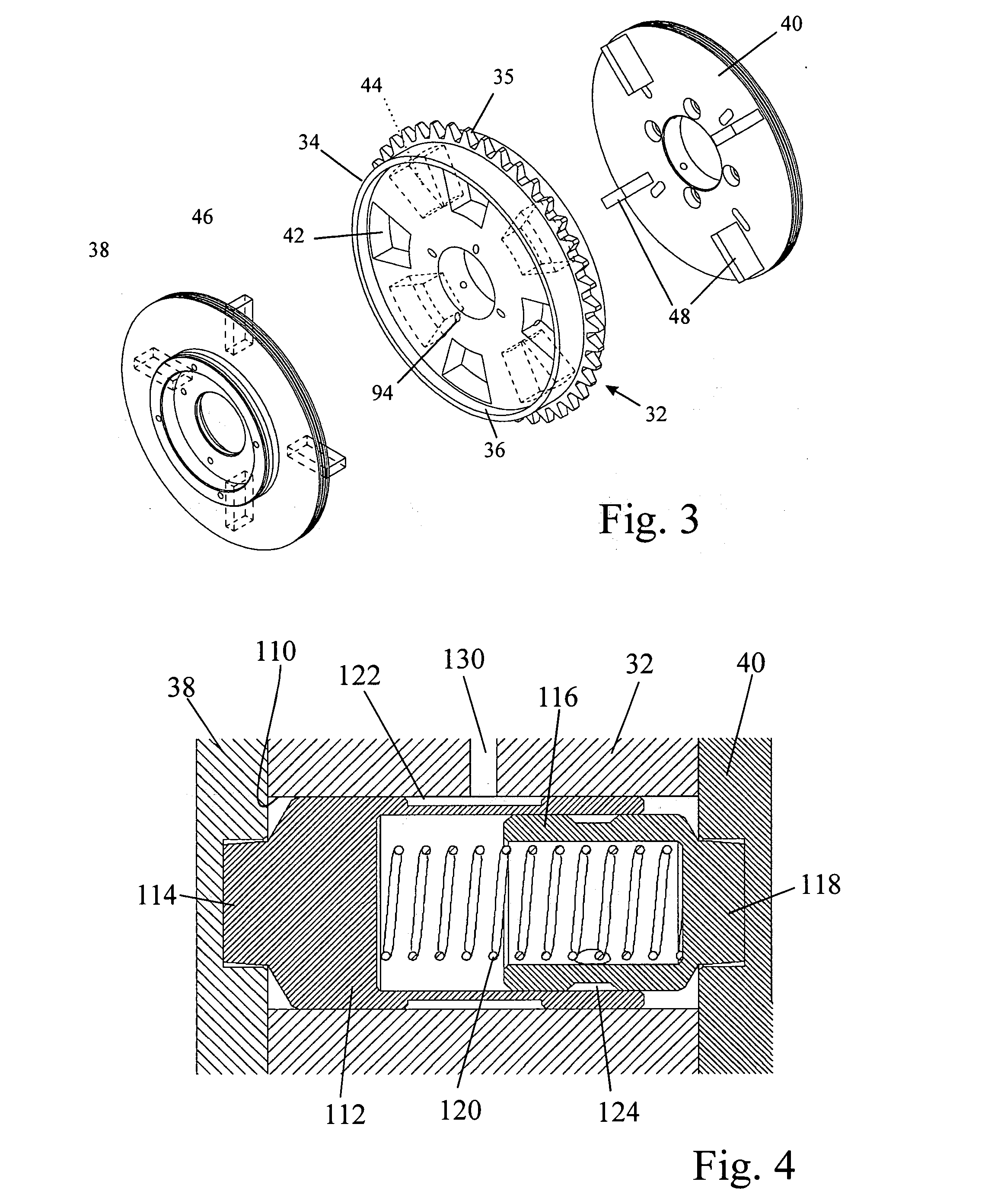
[0030] The end of the inner shaft 14 that projects at the front end of the engine carries the drive sprocket 30. The operation of the phaser in the drive sprocket 30 is best understood from the exploded view shown in FIG. 3. The phaser comprises a drive member 32 in the form of a thick disk 34 which is formed with sprocket teeth 35 and is driven by the engine crankshaft. Of course, the drive member 32 could equally be part of a chain sprocket or a toothed b...


PUM


Abstract

A twin vane-type phaser is described which is provided with a locking mechanism for locking the drive member to the driven members when the pressure in the working chambers is a below is predetermined value. The locking mechanism comprises two coaxial locking pins 114, 118 mounted in a common bore 110 in the centrally located member 32. The locking pins are resiliently urged apart by a spring 120 into bores in the two outer members 38, 40 and are retracted by pistons 112, 116 when the hydraulic pressure in the working chambers attains the predetermined value.

Description

CROSS-REFERENCE TO RELATED APPLICATION [0001] This application claims priority of United Kingdom Patent Application No. 0408127.9 filed Apr. 13, 2004. BACKGROUND OF THE INVENTION [0002] 1. Field of the Invention [0003] The present invention relates to a variable phase drive mechanism, also referred to as a phase change mechanism or still more simply as a phaser. [0004] 2. Description of the Related Art [0005] It is well known to use a phaser in an internal combustion engine to vary the phase of the camshaft(s) in relation that of the crankshaft so as to allow the opening and closing times of the inlet and / or the exhaust valves within the combustion cycle to be varied. Such phasers have a drive member coupled for rotation with the engine crankshaft, one or more driven members each coupled for rotation with the or a respective camshaft and means for rotating the drive member relative to the driven member(s). [0006] Different types of phasers have been proposed in the prior art which a...

Claims


Application Information

Patent Timeline
IPC IPC(8): F01L1/34F01L1/344F04B49/00F04B49/02
CPCF01L1/3442F04B49/022F01L2001/34493F01L2001/34469
Inventor LANCEFIELD, TIMOTHY MARKOWEN, RICHARD ALWYN
Owner MECHADYNE LTD
Why Eureka
Try Eureka