Parameter sensing system for an exercise device

a technology of parameter sensing and exercise equipment, which is applied in gymnastic exercise, digger harvesters, agriculture tools and machines, etc., can solve the problems of difficult for users to enter weight and start the treadmill quickly, the difficulty of adjusting the weight, and the difficulty of properly using the digital electronic control system with embedded software routines and increased functionality,

Inactive Publication Date: 2005-10-13
PRECOR
View PDF21 Cites 35 Cited by
  • Summary
  • Abstract
  • Description
  • Claims
  • Application Information

AI Technical Summary

Benefits of technology

[0012] According to another preferred aspect of the invention, a treadmill includes a frame, a deck assembly, at least one deck deflection sensor, a drive assembly, and a control system. The deck assembly is supported by the frame. The deck assembly includes a longitudinally extending deck, at least first and second rollers, and a belt positioned about the deck and the first and second rollers. The deck deflection sensor is coupled to the deck. The deck deflection sensor is configured to produce a signal representative of a weight applied to the deck. The drive assembly is coupled to one or both of the first and second rollers. The control system is operably coupled to the drive assembly and the deck deflection sensor. The control system configured to prevent the treadmill from operating until the signal received from the at least one deck deflection sensor exceeds a predetermined magnitude.
[0013] According to another preferred aspect of the invention, a treadmill is configured to detect a user's weight. The treadmill includes a frame, a deck assembly, at least one deck deflection sensor, and a control system. The deck assembly is supported by the frame. The deck assembly includes a longitudinally extending deck, and a belt operably supported by the deck. The deck deflection sensor is coupled to the deck. The deck deflection sensor includes at least one transmit winding, at least one receive winding, and an electrical intermediate device. Wherein the application of the user's weight to the deck assembly causes displacement of the electrical intermediate device, which produces a change in mutual inductance between the transmit and receive windings. The control system is operably coupled to the at least one deck deflection sensor. The control system is configured to electrically measure and correlate the change in mutual inductance between the transmit and receive windings into a deck displacement measurement.
[0014] According to another preferred aspect of the invention, a treadmill is configured for operation by a user. The treadmill includes a frame, a deck assembly, at least one aerial, a control system, and first and second electrical intermediate devices. The deck assembly is supported by the frame and includes a longitudinally extending deck, at least first and second rollers, and a belt positioned about the deck and the first and second rollers. The aerial is positioned proximate the deck and includes a set of transmit and receive windings. The control system is operably coupled to the transmit and receive windings. The control system is configured to supply an alternating electrical signal to the transmit windings. The first and second electrical intermediate devices are secured to the right and left legs of the user, respectively. Each intermediate device is config

Problems solved by technology

Despite their widespread use, such existing treadmills have a number of drawbacks.
Many users have difficulty entering their weight and starting the treadmill quickly.
The digital electronic control systems with embedded software routines and increased functionality can sometimes be confusing, or even intimidating, for the user to properly use.
Such confusion or intimidation caused by the machine's sophisticated user interface often effectively presents a barrier to widespread use, particularly by the elderly or technologically unsophisticated or those user's which may become embarrassed from their perceived ignorance in public fitness clubs or gymnasia.
Consequently, the electronic control system is incapable of accurately calculating such useful information as calories burnt or intensity of training during a workout.
Such instances can also present a safety hazard.
Although some existing devices incorporate the use of a tether in order to operate the machine, many find the use of tethers to be difficult to use,

Method used


Image

  • Parameter sensing system for an exercise device
  • Parameter sensing system for an exercise device
  • Parameter sensing system for an exercise device

Examples


Embodiment Construction

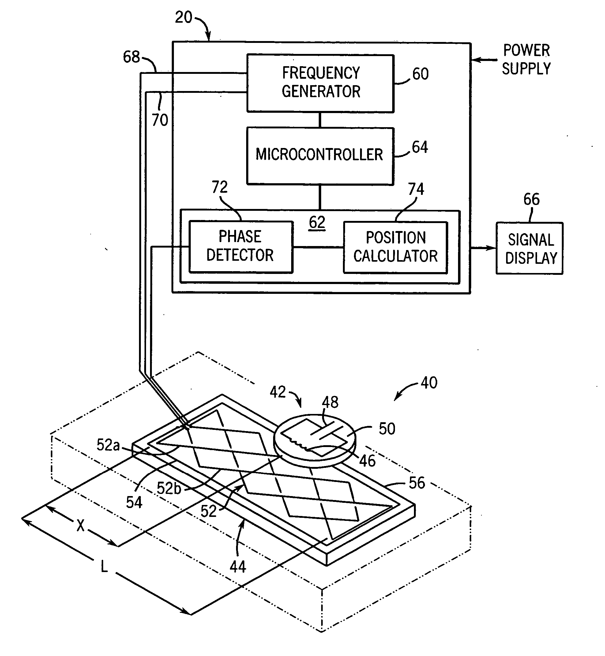
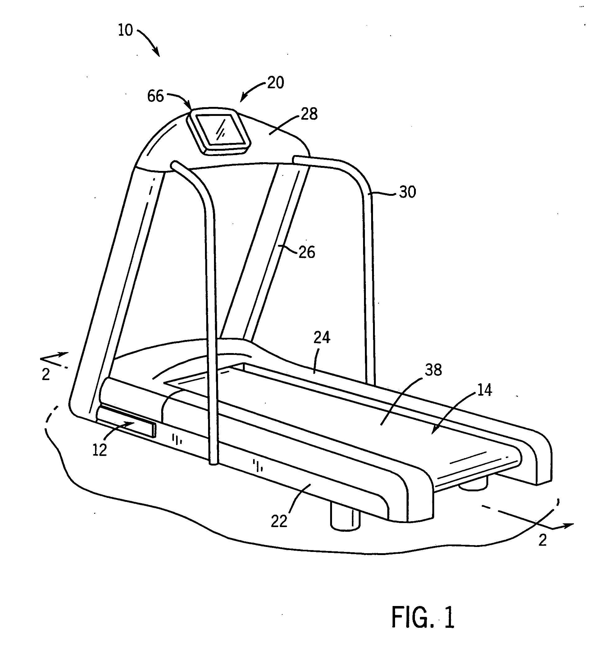
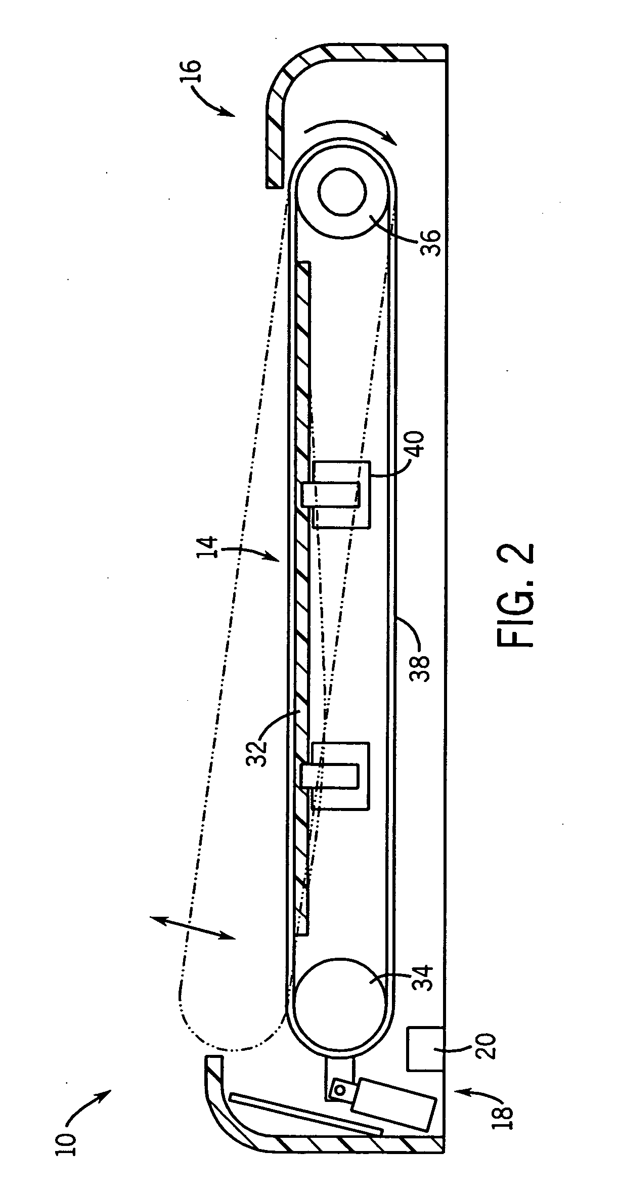
[0027] Referring to FIGS. 1 and 2, an exercise machine, specifically a treadmill, is indicated generally at 10. The present invention is also applicable to other types of exercise machines, such as, for example, an elliptical exercise machine, a stair stepper and a cycling machine. The treadmill 10 includes a frame 12, operably supporting a deck assembly 14, a drive assembly 16, a lift assembly 18 and a control system 20. The frame 12 preferably includes first and second longitudinally extending sides 22 and 24, at least a pair of upwardly extending posts 26 interconnected at an upper end to a support plate 28, which generally spans the width of the deck assembly 14 and supports the control system 20, or a portion thereof. In a preferred embodiment, the frame 12 further includes a cross bar 30 upwardly extending from each side of the deck assembly 14 and extending across the deck assembly 14 adjacent the support plate 28. The frame12 is formed of a tough, rigid, durable material, pr...


PUM


Abstract

A treadmill includes a frame, a deck assembly, at least one deck deflection sensor, and a control system. The deck assembly is supported by the frame. The deck assembly includes a longitudinally extending deck, at least first and second rollers, and a belt positioned about the deck and the first and second rollers. The deck deflection sensor is coupled to the deck. The deck deflection sensor is a contactless displacement sensor including an electrical intermediate device and an aerial. The control system is operably coupled to the at least one deck deflection sensor.

Description

FIELD OF THE INVENTION [0001] This invention relates to instrumentation and electronic control systems for fitness equipment. In particular, the invention relates to a parameter sensing system for exercise equipment. The parameters can include a user's presence and / or a user's position on an exercise device, and the speed and / or angle of inclination, of an exercise device. BACKGROUND OF THE INVENTION [0002] Many types of machines are used for fitness or sport training. Such machines are already known from their wide market availability for domestic, rehabilitation and commercial purposes. Treadmills, or running machines, are one of the most common forms of such machines. Treadmills typically include a support frame, a deck, an endless belt, a drive mechanism and a user interface. The endless belt typically extends over the deck and rotates around the deck and a pair of substantially parallel rollers to simulate the ground moving beneath a user as he or she walks or runs. The user in...

Claims


Application Information

Patent Timeline
IPC IPC(8): A63B22/02A63B23/04A63B24/00A63B22/06A63B69/00A63B71/00
CPCA63B22/0023A63B22/0242A63B22/0285A63B2230/01A63B2220/13A63B2220/51A63B2024/0093
Inventor DYER, DAVID E.WEST, RODNEY P.PIPINICH, VICTOR
Owner PRECOR
Why Eureka
Try Eureka