
System and method for automatically segmenting bones in computed tomography angiography data

a computed tomography and bone structure technology, applied in the field of automatic segmentation of bones in computed tomography angiography data, can solve the problems of ineffective use of methods, inconvenient use of methods, and inability to automatically segment bones,

Inactive Publication Date: 2005-10-13
SIEMENS MEDICAL SOLUTIONS USA INC
View PDF7 Cites 25 Cited by
  • Summary
  • Abstract
  • Description
  • Claims
  • Application Information

AI Technical Summary

Benefits of technology

[0007] The present invention is directed to a system and method for automatically segmenting bone regions from Computed Tomography Angiography (CTA) volume data is disclosed. A locally operated bone detector distinguishes between bone regions and contrast agent filled vessels.

Problems solved by technology

However, due to the overlapping intensity distribution between bone and contrast enhanced vessels in CTA data, bone structures can be a major obstacle in the visualization and analysis of vessel trees, aneurisms and calcifications.
However, the tedious and long operating time required for the manual editing is prohibitive for it to be of practical use.
Semi-automatic methods exist for segmenting bone structures from a focused region of the body; however, these methods are often inefficient for use with large data, or are not sufficiently robust for extension to automatic clinical use cases.
For example, methods that are crucially based on specific industry threshold constraints are generally not robust foundations for segmentation due to the variability of intensities in the different organ parts of a large image and in different data.
Region growing based and other more elaborate graph based methods also pose problems for speed and memory consumption efficiency due to either incoherent data memory access or large memory consumption.
Region growing based methods that rely only on region connectivity and simple constraints such as threshold ranges, also often face challenges when bones and vessels with overlapping intensity distribution also appear to be connected due to image resolution and noise in the data, which is a common case in routine clinical data.
However, even when an anatomical atlas is available as the basis of a priori knowledge, the method still requires lengthy registration and sometimes manual interventions that are still not yet practical for routine use.

Method used


Image

  • System and method for automatically segmenting bones in computed tomography angiography data
  • System and method for automatically segmenting bones in computed tomography angiography data
  • System and method for automatically segmenting bones in computed tomography angiography data

Examples


Embodiment Construction

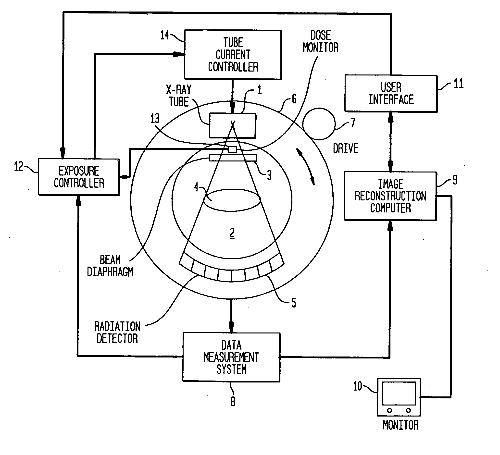
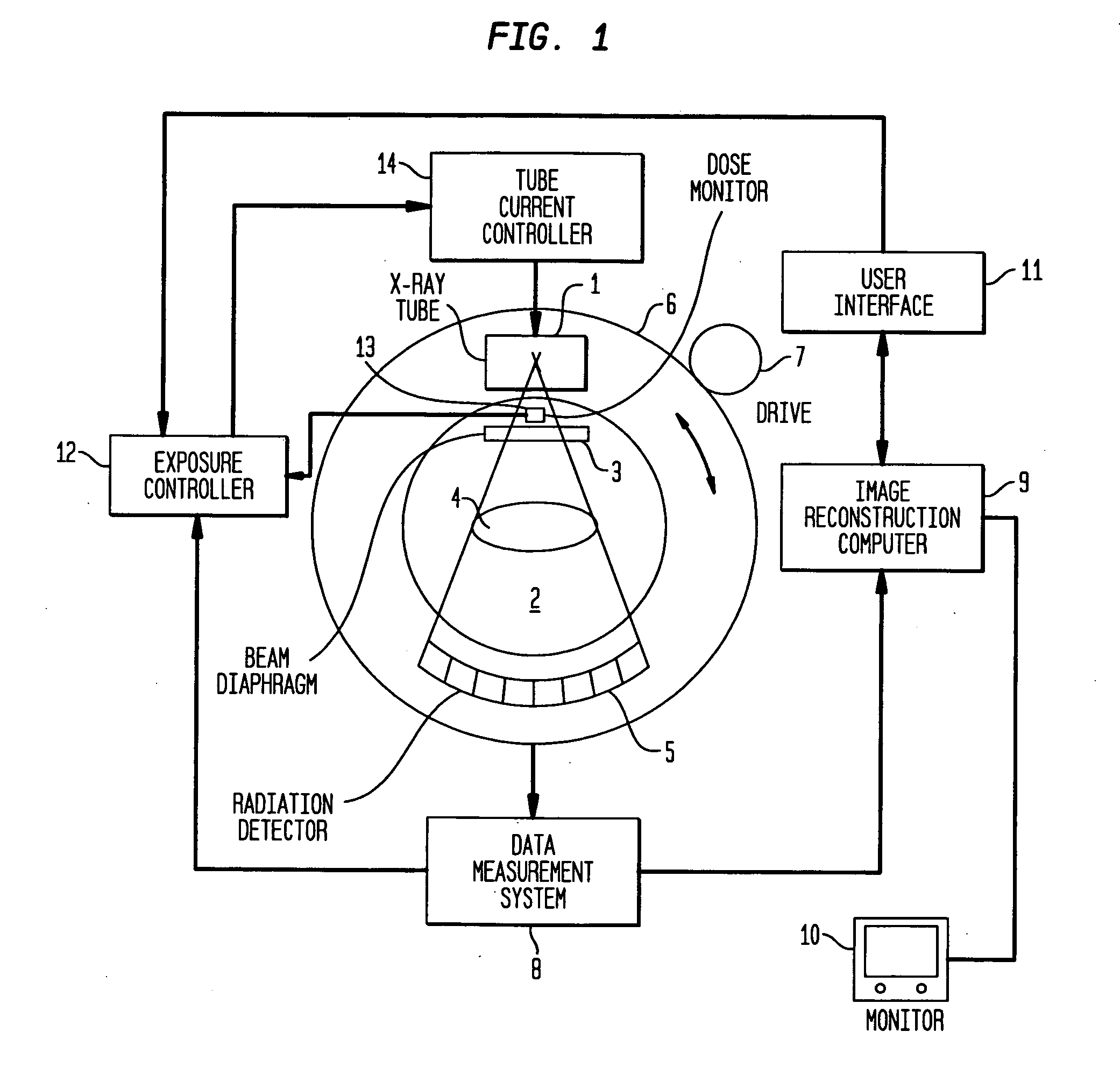
[0016] The present invention is directed to a system and method for automatically segmenting bones in Computed Tomography Angiography (CTA) data. FIG. 1 illustrates a conventional CT system with which the present invention can be practiced. The CT system includes an X-ray tube 1 which emits an X-ray beam 2 from a focus. The X-ray beam 2 is gated by a beam diaphragm 3, and proceeds through an examination subject 4, so as to be incident on a radiation detector 5. The X-rays incident on the radiation detector 5 are attenuated by the examination subject 4, and the radiation detector 5 generates electrical signals corresponding to the attenuated X-ray incident thereon.

[0017] The X-ray tube 1 and the radiation detector 5 are mounted on a rotatable gantry 6, which is rotated by a drive 7. The X-ray beam 2 is therefore caused to rotate around the examination subject 4, so that a series of projections, respectively obtained at different projection angles, are made. Each projection has a dat...


PUM


Abstract

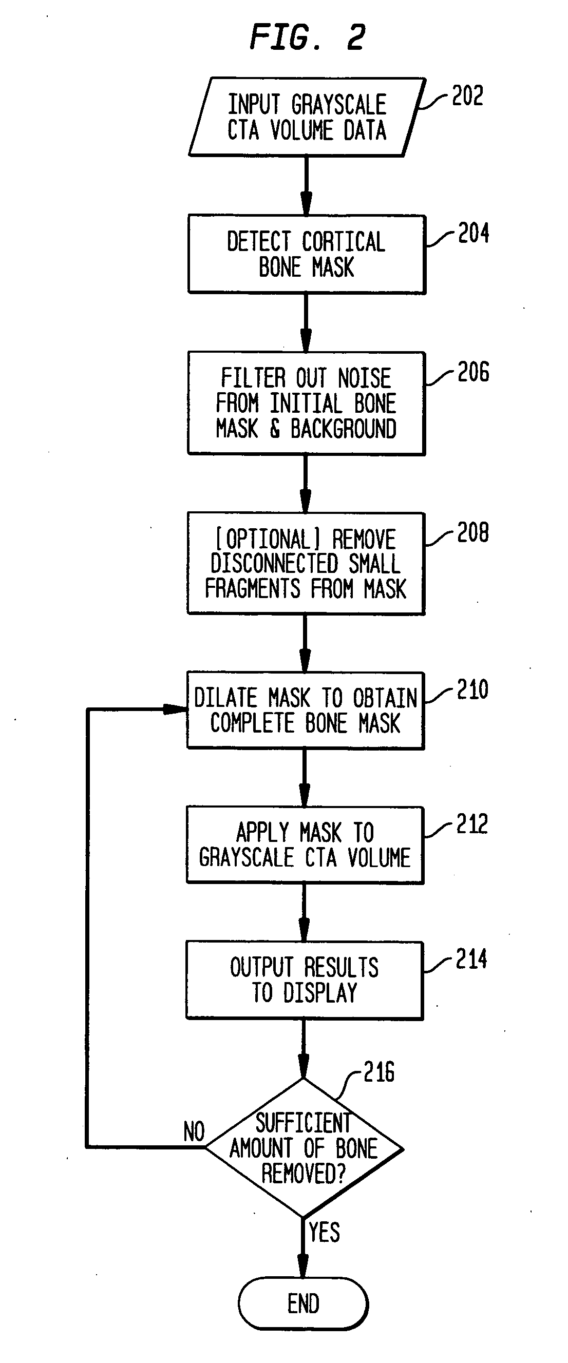
A system and method for automatically segmenting bone regions from Computed Tomography Angiography (CTA) volume data is disclosed. A locally operated bone detector distinguishes between bone regions and contrast agent filled vessels. A filtering operator removes small noise from the detected bone regions. A dilator expands the filtered detected bone regions to adjacent trabecular bones. A processor applies the dilated detected bone regions to the CTA volume data. A display shows the applied CTA volume data.

Description

CROSS REFERENCE TO RELATED APPLICATION [0001] This application claims the benefit of U.S. Provisional Application Ser. No. 60 / 561,187, filed on Apr. 9, 2004, which is incorporated by reference in its entirety.FIELD OF THE INVENTION [0002] The present invention is directed to a system and method for automatically segmenting bones in computed tomography angiography data, and more particularly, to a system and method for automatic bone mask extraction from computed tomography angiography data based on efficient feature detection and filtering methods. BACKGROUND OF THE INVENTION [0003] Visualization and analysis of large three dimensional (3 D) Computed Tomography Angiography (CTA) image data has become a conventional practice. The visualization of data is commonly achieved by a maximum intensity projection or by volume rendering. However, due to the overlapping intensity distribution between bone and contrast enhanced vessels in CTA data, bone structures can be a major obstacle in the...

Claims


Application Information

Patent Timeline
IPC IPC(8): A61B5/05A61B6/00A61B6/03G06T5/00G06T5/50
CPCA61B6/03A61B6/466A61B6/481A61B6/504G06T7/0081G06T7/0091G06T2207/30101G06T2200/04G06T2207/10081G06T2207/20101G06T2207/20224G06T2207/30008G06T7/0097G06T7/11G06T7/155G06T7/174
Inventor YU, DAPHNE
Owner SIEMENS MEDICAL SOLUTIONS USA INC
Learn More