Injector for liquid medicine

a liquid medicine and injector technology, applied in the direction of valves, intravenous devices, other medical devices, etc., can solve the problems of operator health problems, leakage of charged medicine, and difficulty in operation, and achieve the effect of easy operation

Inactive Publication Date: 2005-10-13
NIPRO CORP
View PDF5 Cites 4 Cited by
  • Summary
  • Abstract
  • Description
  • Claims
  • Application Information

AI Technical Summary

Benefits of technology

[0007] It is therefore an object of the present invention to provide an injector for liquid medicine which is easy to operate, makes it possible to continually administer a little dose of a liquid medicine different from a first liquid medicine during administration of the first liquid medicine.
[0017] The injector of the present invention can be used in combination with a syringe for injection of contrast media for myocardial scintigraphy into a vein, or for infusion of hormone preparation into a dialysis circuit for treatment of renal anemia, or for administration of peptide preparations for treatment of osteoporosis, or administration of antitumor agents, or the like. Further, the injector of the present invention can be used, in combination with infusion solution bag or bottle connected thereto with tubing, for administration of vitamin preparation just before infusion of a high-calorie infusion solution to prevent Maillard reaction.

Problems solved by technology

However, use of the three-way stopcock or Y-shaped tube may cause leakage of the charged medicine at the time of connection of the prefilled syringe or priming operation.
In particular, in case of medicines such as antitumor agents which are high in carcinogen, the leakage of such a medicine may causes health problems of the operator.
Further, the administration of a little dose of expensive medicine is difficult to operate and makes it difficult to perform effective administration since the medicine may be diluted with other medicine.
In addition, there is a problem such that the medicine is remained in route of administration.

Method used


Image

  • Injector for liquid medicine
  • Injector for liquid medicine
  • Injector for liquid medicine

Examples


Embodiment Construction

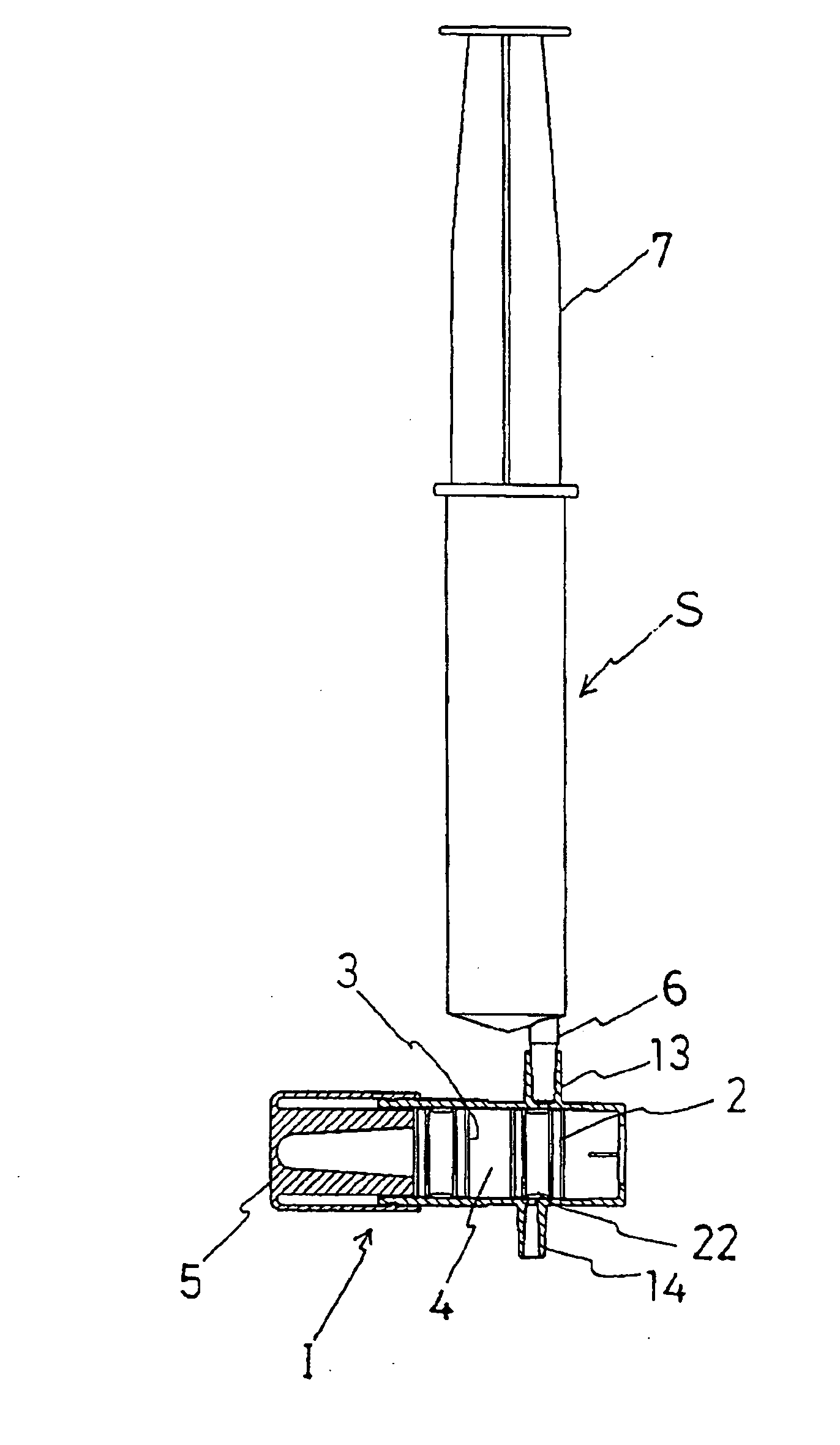
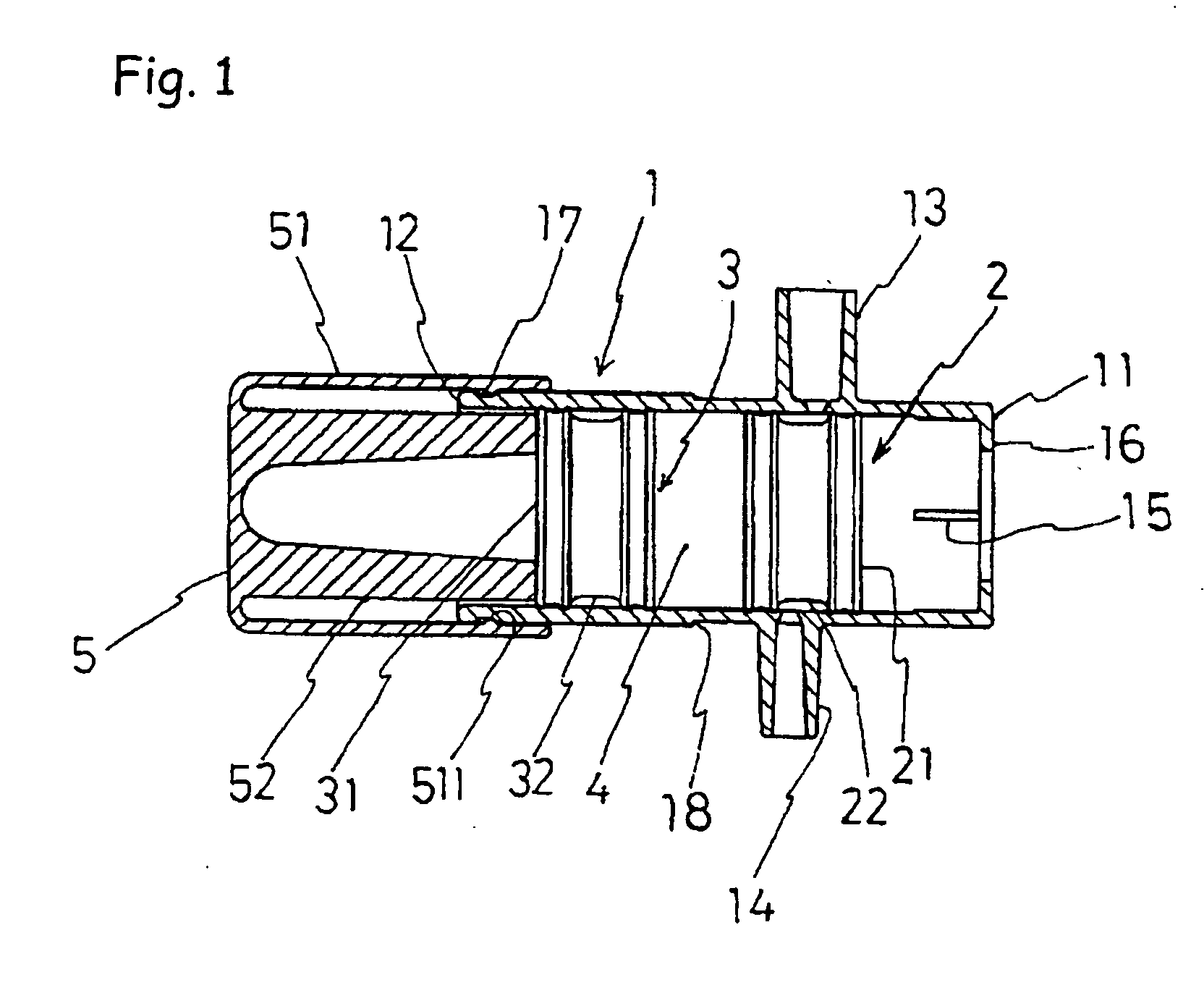
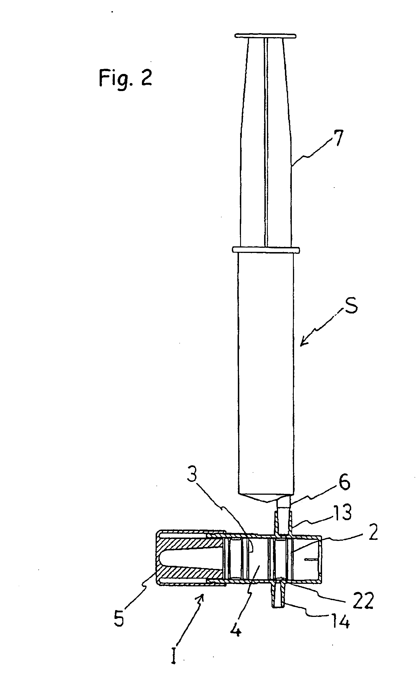
[0025] As illustrated in FIGS. 1, 6 and 10, an injector of the present invention generally comprises a cylindrical body 1, a first gasket 2 contained in a lumen of the cylindrical body 1 and arranged on the side of the distal end thereof, and a second gasket 3 contained in the lumen of the cylindrical body 1 and arranged on the side of the proximal end thereof. The cylindrical body 1 is provided with a fluid inlet 13 and a fluid outlet 14 in opposite sides of the cylindrical body 1 with respect to the longitudinal axis thereof. The second gasket 3 is spaced from the first gasket 2 to form a fluid chamber 4 between them, which is filled with a liquid medicine. The first gasket 2 is adapted to be moved by sliding along the inner wall of the cylindrical body 1 from a first position to a distal end of the cylindrical body 1 via a second position. At the first position, the first gasket 2 allows the fluid inlet 13 to be fluid-communicated with the fluid outlet 14 through the flow path 22...


PUM


Abstract

An injector for liquid medicine comprises a cylindrical body 1, first and second gasket 2, 3 contained in a lumen of cylindrical body 1. The cylindrical body 1 is provided with a fluid inlet 13 and a fluid outlet 14 in opposite sides of the cylindrical body 1 with respect to the longitudinal axis thereof. Second gasket 3 is spaced from the first gasket 2 to form a fluid chamber 4 between them. The first gasket 2 is adapted to be moved by sliding along the inner wall of the cylindrical body 1 from a first position to the distal end 11 of cylindrical body 1 via a second position. The fluid inlet 13 is opened at a position closer to the distal end 11 of the cylindrical body 1 than the outlet 14 is. The first gasket 2 is stopped at a second position where the fluid chamber 4 is communicated with the fluid outlet 14 but prevented from fluid-communication with the fluid inlet 13.

Description

BACKGROUND OF THE INVENTION [0001] 1. Field of the Invention [0002] The present invention relates to an injector for liquid medicine and, more particularly, an injector which enables to continually administer a little dose of a liquid medicine after priming. The injector of the present invention is useful for administration of an additional medicine in midstream of administration of one medicine and for administration of a medicine which may cause infection of an operator during mixed administration of different medicines such as antitumor agents. [0003] 2. Background Art [0004] When performing administration of a liquid medicine with an infusion set or a catheter, it is frequently necessary to administer another medicine in midstream of administration. Such operations are required, for example, in administration of contrast media, hormone preparations, peptide preparations, antitumor agents, vitamin preparations, etc. This is generally done using a prefilled syringe, i.e., a syring...

Claims


Application Information

Patent Timeline
Patent Type & Authority Applications(United States)
IPC IPC(8): A61M5/14A61M39/22
CPCA61M39/223A61M5/1408A61M5/284A61M5/345
Inventor HASEGAWA, MITSURU
Owner NIPRO CORP
Why Eureka
Try Eureka