Delivery and recovery system for embolic protection system

a technology of embolism protection and delivery system, which is applied in the field of improving the efficiency of the delivery and recovery of emboli, can solve the problems of affecting the patient's health, affecting the patient's recovery, so as to achieve the effect of a higher degree of confidence in the efficient delivery and recovery

Inactive Publication Date: 2005-10-13
ANDREWS CHRISTOPHER C +10
View PDF100 Cites 47 Cited by
  • Summary
  • Abstract
  • Description
  • Claims
  • Application Information

AI Technical Summary

Benefits of technology

[0015] The present invention, in general, provides a system and method for the insertion and removal of a filtering system for capturing and retaining embolic debris from a blood vessel. The embolic debris may be created during the performance of a therapeutic interventional procedure, such as a balloon angioplasty or stenting procedure. The filtering system is adapted to prevent the embolic debris from lodging and blocking blood vessels downstream from the interventional site. The present invention is particularly useful for enabling an interventional procedure to be performed in vital arteries, such as the carotid arteries, in which critical downstream blood vessels can become blocked with embolic debris, including the main blood vessels leading to the brain or other vital organs. As a result, the present invention provides the physician with a higher degree of confidence in the efficient delivery and recovery of a filtering system for the collection and removal of embolic debris from the blood vessel when performing high-risk interventional procedures.
[0016] The present invention enables a filtering system to be deployed in the blood vessel at a location distal to the area of treatment in the interventional procedure site. It also enables the blood to pass therethrough to enable blood to flow past the filter. It further enables the blood to be filtered to capture and retain any embolic debris which may be created during the interventional procedure.
[0017] More particularly, for example, in an embodiment of the present invention, a system is adapted to enable at least one operator to control the delivery of an embolic protection device to a position in a patient's vasculature distal to an interventional procedure site, for deployment of the embolic protection device. The present invention also enables the operator to control the removal of the delivery system from the patient's vasculature, to enable the exchange of the delivery and recovery system. It further enables the operator to control the position of a deployed embolic protection device within the patient's vasculature during an exchange of interventional devices.

Problems solved by technology

However, there is one common problem associated with all of these non-surgical procedures, namely, the potential release of embolic debris into the bloodstream which can occlude distal vasculature and cause significant health problems to the patient.
Additionally, while complete vaporization of plaque is the intended goal during a laser angioplasty procedure, particles are not always fully vaporized and may enter the bloodstream.
When any of the above-described procedures are performed for example in the carotid arteries, the release of emboli into the circulatory system can be extremely dangerous to the patient.
Debris that is carried by the bloodstream to distal vessels of the brain may cause these cerebral vessels to occlude, resulting in a stroke, and in some cases, death.
Therefore, although carotid percutaneous transluminal angioplasty has been performed in the past, the number of procedures performed has been limited due to the justifiable fear of causing an embolic stroke should embolic debris enter the bloodstream and block vital downstream blood passages.
However, it is often difficult to control the size of the fragments which are formed, and the potential risk of vessel occlusion still exists, making such procedures in the carotid arteries a high-risk proposition.
However, as mentioned above, there have been complications with such systems since the vacuum catheter may not always remove all of the embolic material from the bloodstream, and a powerful suction could cause problems to the patient's vasculature.
Further techniques which have had some limited success include the placement of an embolic protection device such as a filter or trap downstream from the treatment site to capture embolic debris before it reaches the smaller blood vessels downstream.
However, there have been problems associated with embolic protection devices, particularly during the insertion, expansion, deployment, and removal of the embolic protection device within the blood vessel.
This can sometimes prove to be a somewhat inefficient and inconvenient method for inserting and removing filtering systems.
Further, very substantial pullback force on the guide wire and catheter was required, due to the operation of frictional forces and the interaction thereof.
Also, the insertion and removal of embolic protection devices through a patient's vasculature, if not properly implemented, subjected the patient's vasculature to potential trauma and would interfere with the treatment of the stenosis while increasing the likelihood of damage thereto.

Method used


Image

  • Delivery and recovery system for embolic protection system
  • Delivery and recovery system for embolic protection system
  • Delivery and recovery system for embolic protection system

Examples


first embodiment

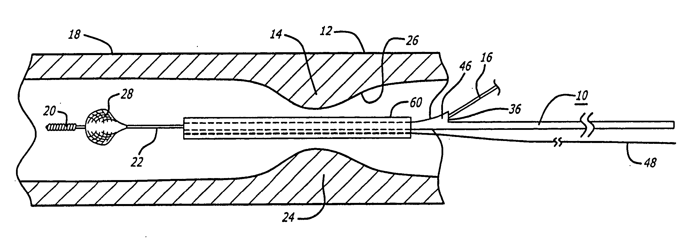
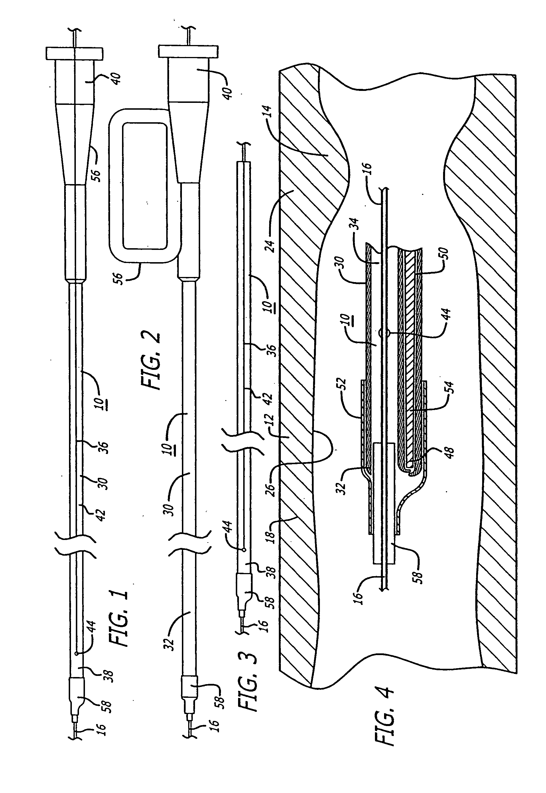
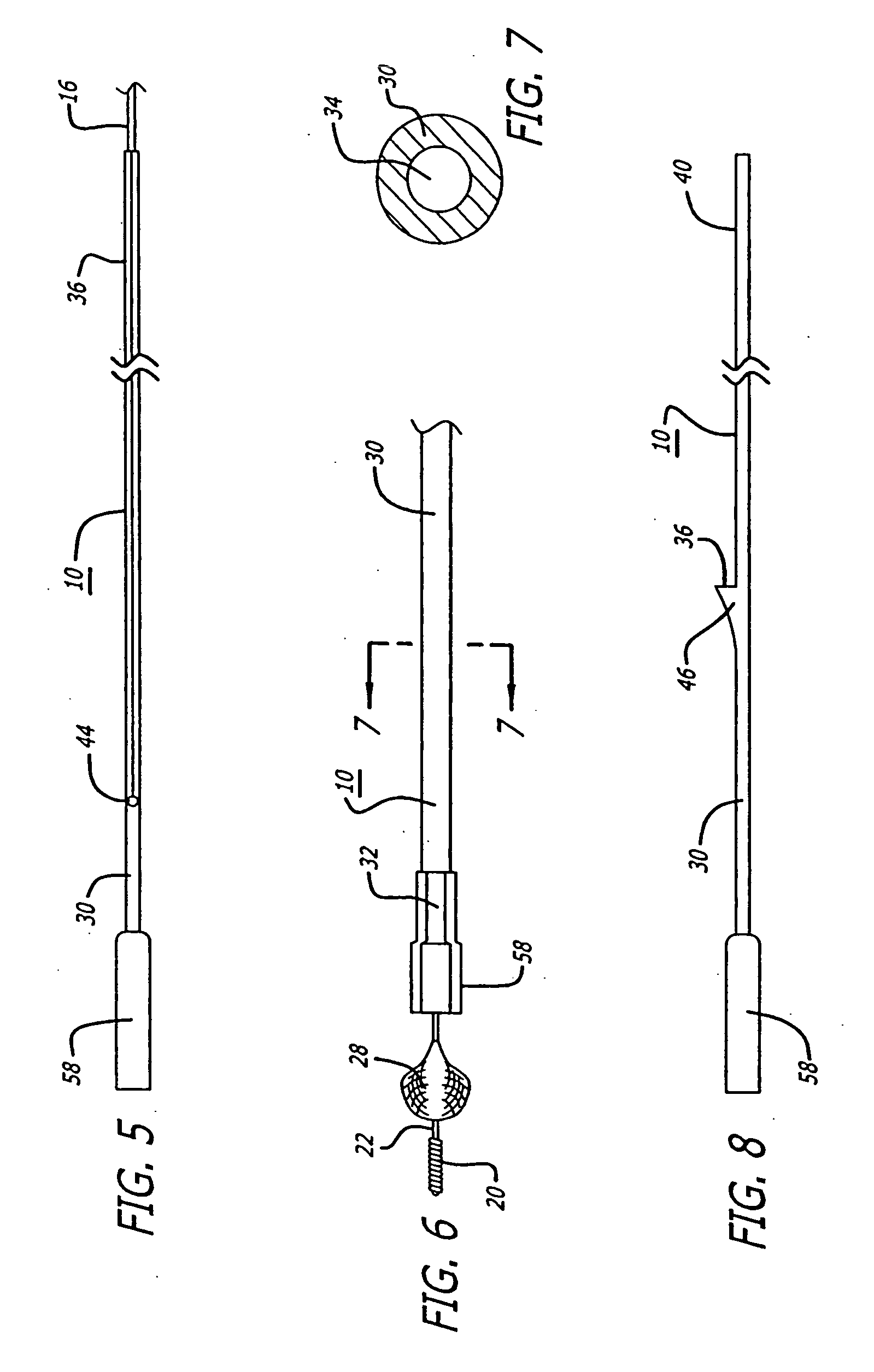
[0058] Referring to FIGS. 1-18, in a system pursuant to the present invention, for example, the system 10 is adapted to enable at least one operator to control of the delivery of the embolic protection device 28 to the position in a patient's blood vessel 12 distal to the area of treatment 14, for deployment of the embolic protection device 28. The system 10 is further adapted to enable the at least one operator to control the removal of the delivery system 10, to enable the exchange of the delivery system, and to enable the control of the position of a deployed embolic protection device 28 within the patient's vasculature 12 during an exchange of interventional devices. The system 10 is further adapted to enable the at least one operator to control the removal of the embolic protection device 28 through the patient's vasculature 12, from the delivered and deployed position thereof, for the exchange of the recovery system.

[0059] As illustrated in FIGS. 1-9, in a delivery version of ...

second embodiment

[0068] Referring to FIGS. 19-26, in a system pursuant to the invention, for example, a system 64 is provided for enabling the delivery and recovery of an embolic protection device 28 relative to a position in the patient's vasculature 12 distal to an interventional procedure site 14, through the patient's vasculature 12, for deployment of the embolic protection device 28. The system 64 is adapted to maintain a clinically acceptable profile and flexibility during the delivery and removal thereof through the patient's vasculature 12. Elements of the system 64 are comprised of polymer materials such as for example PeBax which is comprised of a thermoplastic polyimide. Also, for the delivery of the embolic protection device 28, the materials are such as to provide substantial flexibility for enabling delivery thereof through the patient's anatomy and for preventing the guide wire 16 from kinking, while providing sufficient rigidity for enabling substantial pushing force to be exerted fo...


PUM


Abstract

A system for enabling the insertion and removal of an embolic protection device, for capturing and retaining embolic debris which can be created during the performance of a therapeutic interventional procedure in a stenosed or occluded region of a blood vessel. The system, in an embodiment thereof, is capable of enabling at least one operator to control the delivery and removal of an embolic protection device to a position in a patient's vasculature distal to an interventional procedure site, to enable the exchange of the delivery and recovery system. The system, in another embodiment thereof, includes a delivery system and a recovery system which are capable of enabling the delivery and recovery of an embolic protection device so as to maintain a clinically acceptable profile and flexibility through the patient's vasculature.

Description

CROSS-REFERENCES TO RELATED APPLICATIONS [0001] This is a divisional application of co-pending application Ser. No. 09 / 872,692, filed Jun. 1, 2001, whose contents are hereby incorporated by reference.BACKGROUND OF THE INVENTION [0002] The present invention relates generally to improvements in embolic protection systems and methods. In particular, it relates to an improved system and method for enabling at least one operator to effectively deliver an embolic protection device to a position in a patient's vasculature distal to an interventional procedure site. The deployment of the embolic protection device is enabled so as to filter the blood in a blood vessel, to capture embolic material that may be created and released into the bloodstream during the performance of the interventional procedure in a stenosed or occluded region of a blood vessel. The invention also enables the operator to efficiently remove the embolic protection device from the interventional procedure site with the...

Claims


Application Information

Patent Timeline
Patent Type & Authority Applications(United States)
IPC IPC(8): A61F2/01A61F2/06A61M29/00
CPCA61F2/013A61F2002/011A61F2230/0006A61F2002/018A61F2230/008A61F2/011
Inventor ANDREWS, CHRISTOPHER C.BOYLE, WILLIAM J.CORREA, SERGIODENISON, ANDY E.HUTER, BENJAMIN C.HUTER, SCOTT J.JORDAN, BRADMULLER, PAULNEALE, PAUL V.PATEL, SAMIRSTACK, RICHARD
Owner ANDREWS CHRISTOPHER C
Why Eureka
Try Eureka