Attitude detection method and apparatus for initial motion control
Active Publication Date: 2005-10-13
WESTINGHOUSE AIR BRAKE TECH CORP
View PDF16 Cites 6 Cited by
- Summary
- Abstract
- Description
- Claims
- Application Information
AI Technical Summary
Benefits of technology
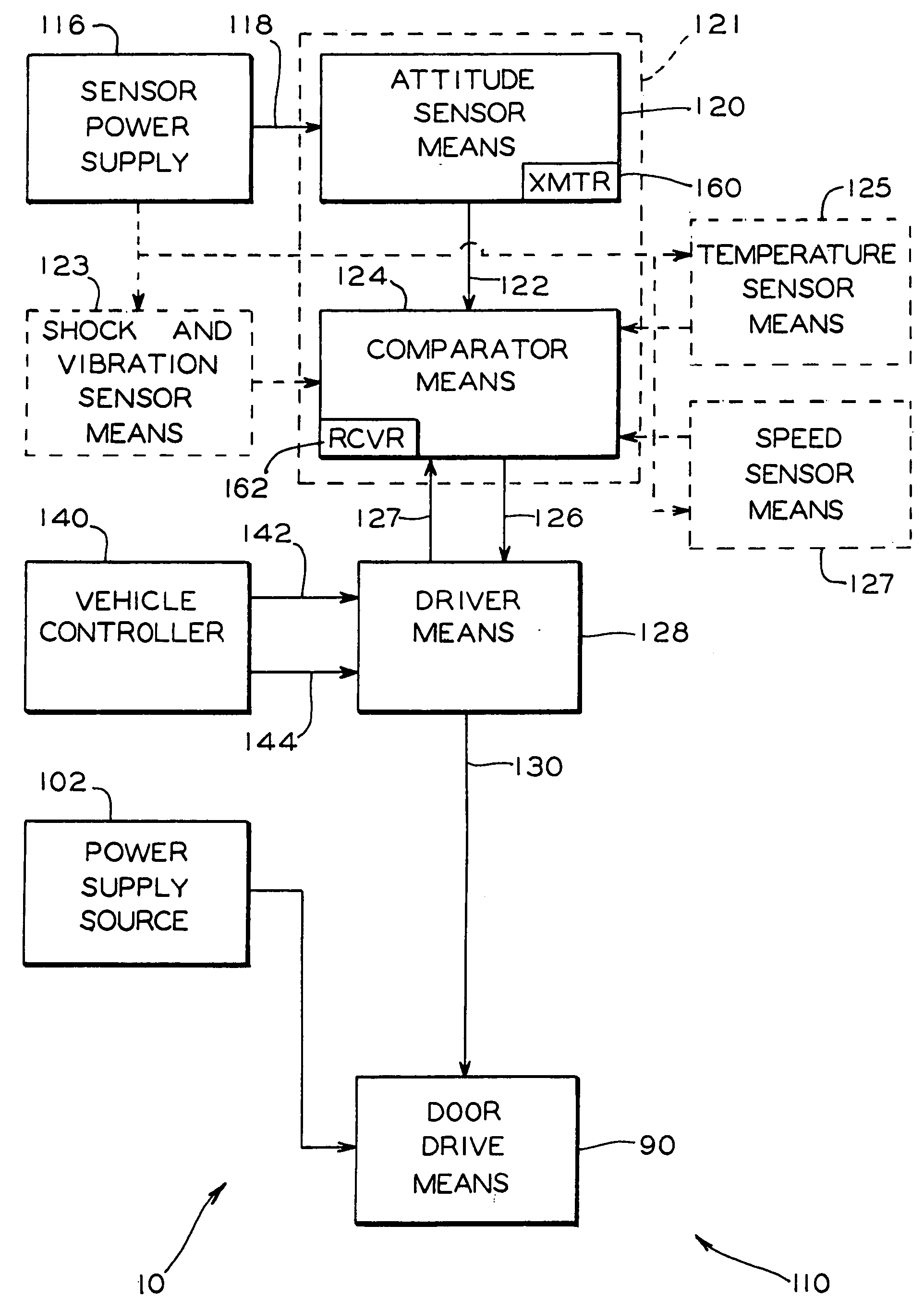
[0020] The present invention overcomes the aforementioned disadvantages of the present control systems by employing an apparatus for measuring a directional attitude of
Problems solved by technology
In many instances changing attitude levels may affect proper movement of the load if such attitude is not compensated for prior to the load movement.
On the other hand, when the vehicle is rolled away from its side used for passenger ingress and egress, the door will tend to open slower and close faster due to its own weight.
As would normally be expected, a much more severe condition for movement of the door is encountered when the transit vehicle is stopped on the terrain surface which combines both roll and pitch attitudes.
In a third aspect, if a transit vehicle exhibits higher rolling levels due to lower tire pressure and / or wheel wear, a door of a larger size may obstructed against a stationary object such as a curb or platform.
These requirements are especially challenging to meet with pneumatic type door systems due to inherent system response delays and pressure fluctuations of the air pressure supply.
However, older and less sophisticated hydraulic or pneumatic control systems employ on / off discrete pressure valve controls and thus lack the ability to respond to fluctuating operational parameters.
A disadvantage of presently used motion control methods is that the door accelerates and decelerates during the range of the motion to achieve a predetermined motion control profile and complete such motion in a predetermined time interval.
Even though door accelerations and decelerations may not be obvious to one observing door motion, they may decrease component durability by diminishing door movement with a constant speed value.
Such an approach further places additional constraints onto an obstruction detection algorithm executed by the control system as it now has to determine whether parameter fluctuations are due to obstruction or are due to other factors such as vehicle attitude described below.
The presently employed control systems lack a capability to recognize abovementioned surface attitudes prior to initiating door movement thus resulting in increased motion corrections during the range of the movement.
This further affects the ability of the door to move within a predetermined time interval, especially at the lower end of the range, and additionally affects movement synchronicity of a plurality of doors on the vehicle.
Such shock and vibration levels increase the initial resistance to movement and further affect timing of the door movement.
Method used
View moreImage
Smart ImageViewing Examples
Examples
first embodiment
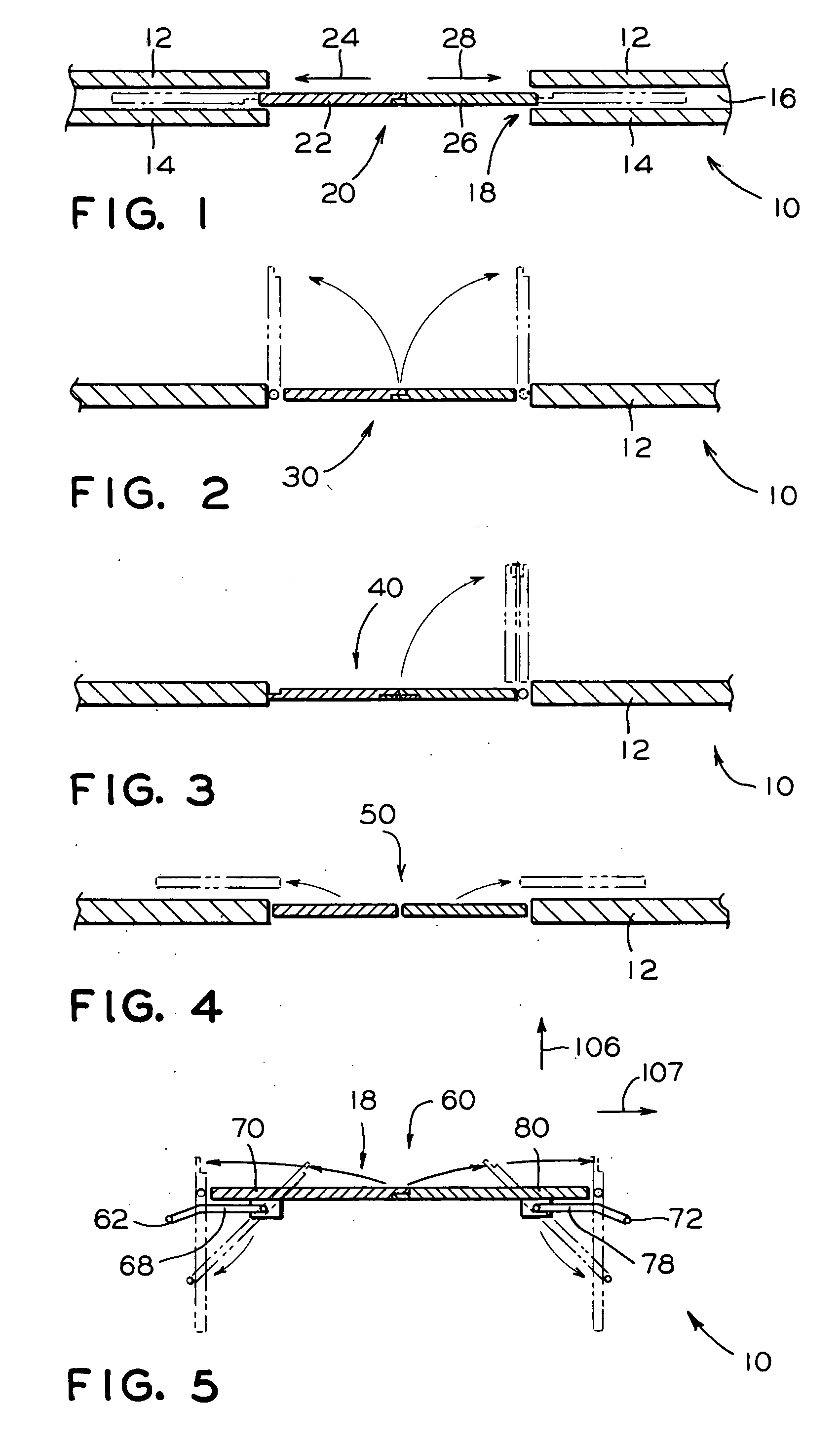
[0037]FIG. 7 is a schematic diagram of the present invention;
second embodiment
[0038]FIG. 8 is a schematic diagram of the present invention; and
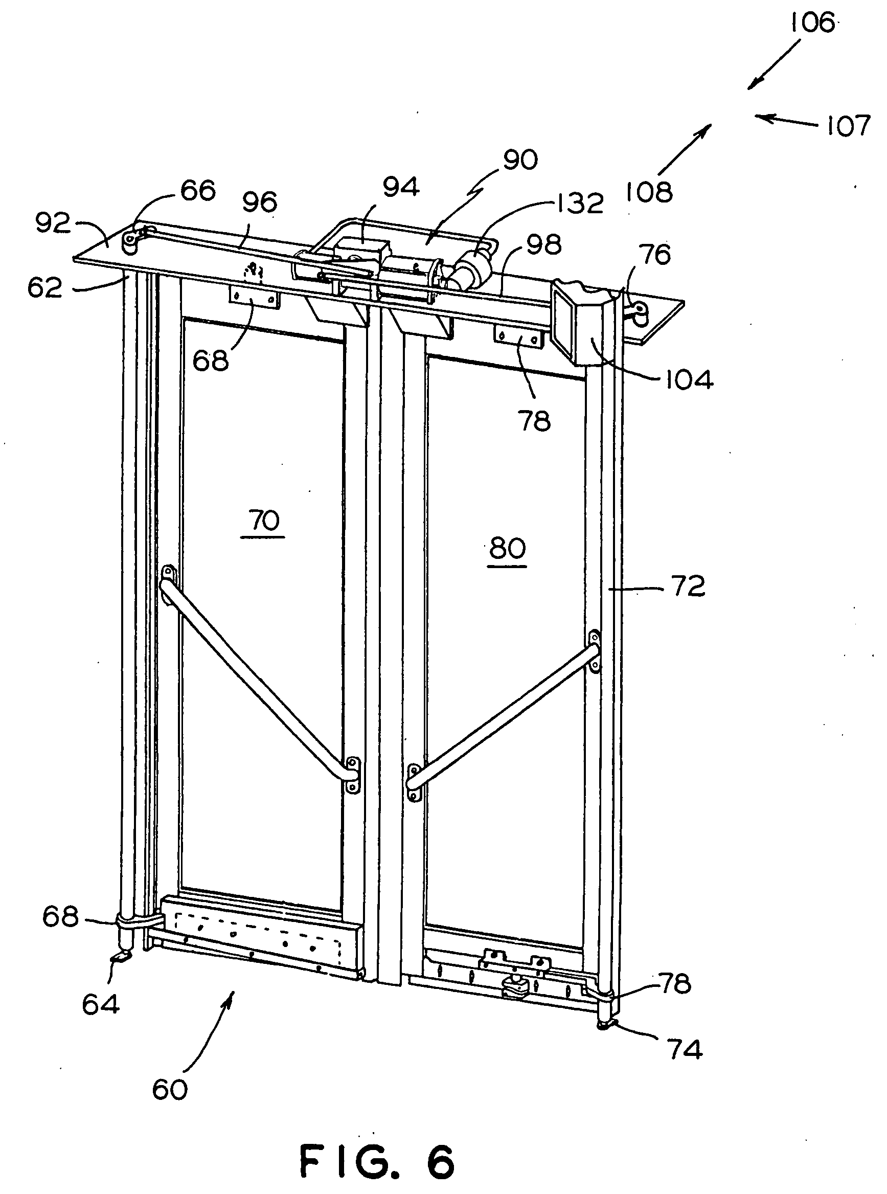
[0039]FIG. 9 is a schematic diagram of a presently preferred embodiment of the invention.
Login to View More PUM
 Abstract
An apparatus and method for measuring a directional attitude of a driven load in respect to a level plane is employed to adjust initial driving power requirements in order to overcome the effects of such attitude. The apparatus employs a sensor for measuring the attitude, a processor for comparing the measurement against a threshold and a driver for altering the initial driving power requirements. Additional sensors for measuring shock, vibration, and temperature levels that the load is subjected to prior to the movement may be employed for calibration of the directional attitude measuring sensor or for further adjustment of the initial driving power requirements.
Description
FIELD OF THE INVENTION [0001] The present invention relates, in general, to initial motion control of moving a load over a predetermined path having an attitude and, more particularly, the instant invention relates to initial motion control of a powered door for a vehicle, and yet, more particularly, the present invention relates to initial motion control of a powered door for a transit vehicle door system. BACKGROUND OF THE INVENTION [0002] The following background information is being provided to assist the reader in understanding the environment in which the invention will typically be used. The terms used herein are not intended to be limited to any particular narrow interpretation unless specifically stated otherwise in this document. [0003] Examples of moving a load over a predetermined path which also varies in a vertical direction, hereinafter referred to as an attitude, include an apparatus for moving a work holding table for metal cutting equipment, a powered apparatus for...
Claims
Login to View More Application Information
Patent Timeline
 IPC IPC(8): B60J5/06B60J7/057E05F15/02E05F15/10
CPCB60J5/062E05Y2900/51E05F15/603E05Y2400/31E05F15/50E05Y2400/44
Inventor URMAN, ROBERTCITTA, JAMES W.RODDY, WARREN D.
Owner WESTINGHOUSE AIR BRAKE TECH CORP
- R&D Engineer
- R&D Manager
- IP Professional
Why Eureka
- Industry Leading Data Capabilities
- Powerful AI technology
- Patent DNA Extraction
Eureka Blog
Learn More Browse by: Latest US Patents, China's latest patents, Technical Efficacy Thesaurus, Application Domain, Technology Topic, Popular Technical Reports.
© 2024 PatSnap. All rights reserved.Legal|Privacy policy|Modern Slavery Act Transparency Statement|Sitemap|About US| Contact US: help@patsnap.com


