Stent crimper

a crimper and stent technology, applied in the field of stent crimpers, can solve problems such as the change in the size of the chamber, and achieve the effect of minimizing the distortion

Active Publication Date: 2005-10-20
BOSTON SCI SCIMED INC
View PDF79 Cites 120 Cited by
  • Summary
  • Abstract
  • Description
  • Claims
  • Application Information

AI Technical Summary

Benefits of technology

[0008] It would be desirable to produce a device capable of crimping a stent while minimizing the distortion of, and scor

Problems solved by technology

Rotation of the mount may cause a

Method used


Image

  • Stent crimper
  • Stent crimper
  • Stent crimper

Examples


Embodiment Construction

[0049] While this invention may be embodied in many different forms, there are described in detail herein by way of illustration, specific embodiments of the invention. This description is an exemplification of the principles of the invention and is not intended to limit the invention to the particular embodiments illustrated.

[0050] Any US patents, US applications and all other published documents mentioned anywhere in this application are incorporated herein by reference in their entireties.

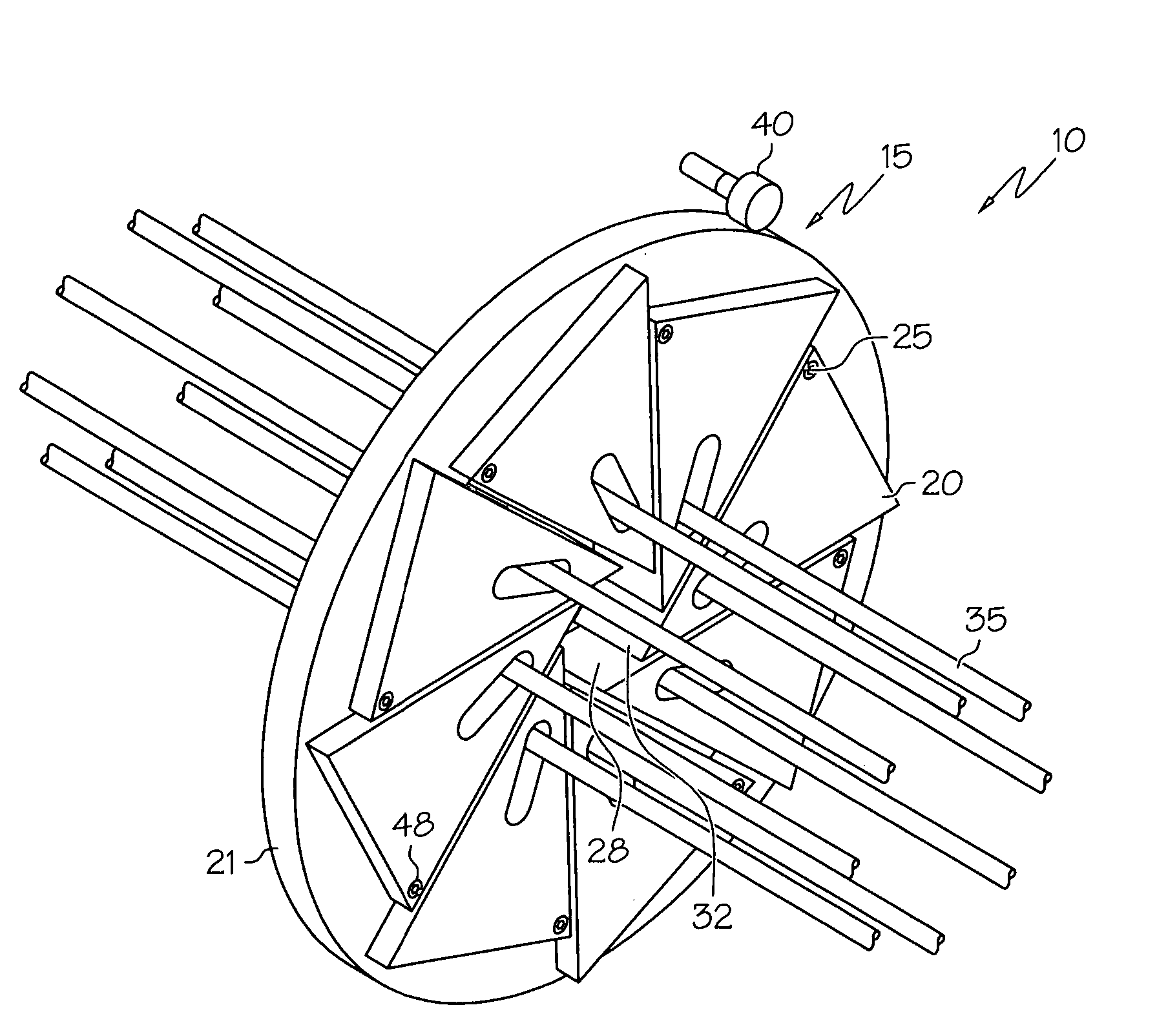
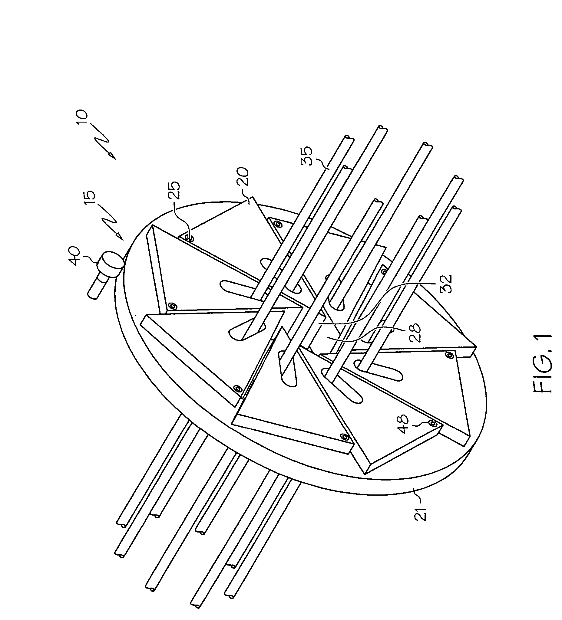
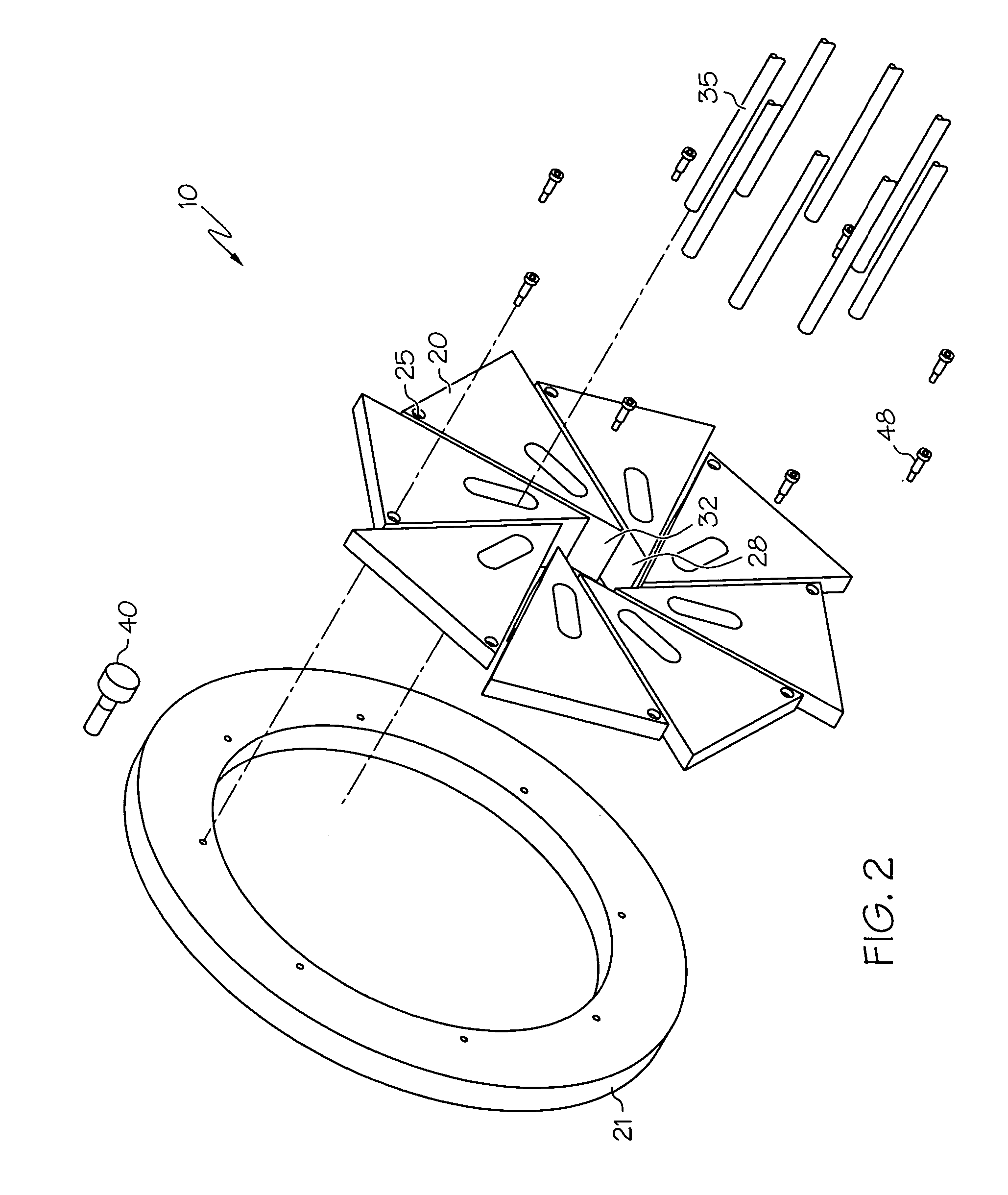
[0051] The term crimping, as used herein, refers to a reduction in size or profile of an article, such as a medical device.

[0052] In the description that follows it is understood that the invention contemplates crimping a medical device either directly about a catheter tube or to a catheter balloon which is disposed about a catheter tube. When reference is made to crimping a medical device about a catheter, a balloon may be situated between the medical device and the catheter tube or the medi...


PUM

PropertyMeasurementUnit
Timeaaaaaaaaaa
Lengthaaaaaaaaaa
Forceaaaaaaaaaa

Abstract

An apparatus for applying an inward force to a medical device may include at least two independently operable sections. Each section may include a plurality of movable blades arranged to form an aperture or chamber whose size may be varied. Each blade may be pivotally connected to a mount and slidably engaged with a constraining member. The blades are movable so as to allow the aperture to be sized to contain the medical device and to alter the size of the aperture.

Description

BACKGROUND OF THE INVENTION [0001] Stents and stent delivery assemblies are utilized in a number of medical procedures and situations, and as such their structure and function are well known. A stent is a generally cylindrical prosthesis introduced via a catheter into a lumen of a body vessel in a configuration having a generally reduced diameter and then expanded to the diameter of the vessel. In its expanded configuration, the stent supports and reinforces the vessel walls while maintaining the vessel in an open, unobstructed condition. [0002] Stents are available in both self-expanding and inflation or balloon expandable configurations. Inflation expandable stents are well known and widely available in a variety of designs and configurations. Both self-expanding and inflation expandable stents are typically crimped to their reduced configuration after being disposed about a delivery catheter. They are maneuvered to the deployment site and expanded to the vessel diameter either by...

Claims


Application Information

Patent Timeline
IPC IPC(8): A61F2/06A61F2/84B21D41/00
CPCA61F2/958Y10T29/53996A61F2002/9522A61F2/9522A61F2/9524
Inventor PERREAULT, DANIEL
Owner BOSTON SCI SCIMED INC
Why Eureka
Try Eureka