Knock sensor

a technology of knock sensor and output, which is applied in the direction of acceleration measurement using interia force, machines/engines, instruments, etc., can solve the problem of superimposed noise on the output of the knock sensor, and achieve the effect of stable output and changeable electrostatic capacity of the piezoelectric elemen

Active Publication Date: 2005-10-20
MITSUBISHI ELECTRIC CORP +1
View PDF2 Cites 13 Cited by
  • Summary
  • Abstract
  • Description
  • Claims
  • Application Information

AI Technical Summary

Benefits of technology

[0014] Since the knock sensor of this invention is constructed as described above, the electrostatic capacity of the piezoelectric element can be changed by changing the area of the partial electrode of the piezoelectric element, and the knock sensors having different output sensitivities can be obtained to have the same outer shape. Further, the knock sensor can prevent discharge to the terminal plate by electric charges generated in the electrodeless part of the piezoelectric element by a pyro effect caused by temperature change, and it becomes possible to obtain such a stable output that noise is not superimposed even when temperature change occurs.
[0015] Besides, it becomes possible to adopt a manufacturing method in which the coating of the electric insulating material is reasonably and uniformly applied to the piezoelectric element or the terminal plate.

Problems solved by technology

However, it has been found that when the piezoelectric element 4 is made to have partial electrodes, since a gap corresponding to the thickness of the partial electrode exists between the piezoelectric element 4 and the terminal plates 5 and 6, there are following problems.
As stated above, in the case where the electrode of the piezoelectric element is made the partial electrode in the structure of the conventional knock sensor, there is a problem that noise is superimposed on the output of the knock sensor.

Method used


Image

  • Knock sensor
  • Knock sensor
  • Knock sensor

Examples


embodiment 1

[0024] Hereinafter, embodiment 1 of this invention will be described with reference to the drawings.

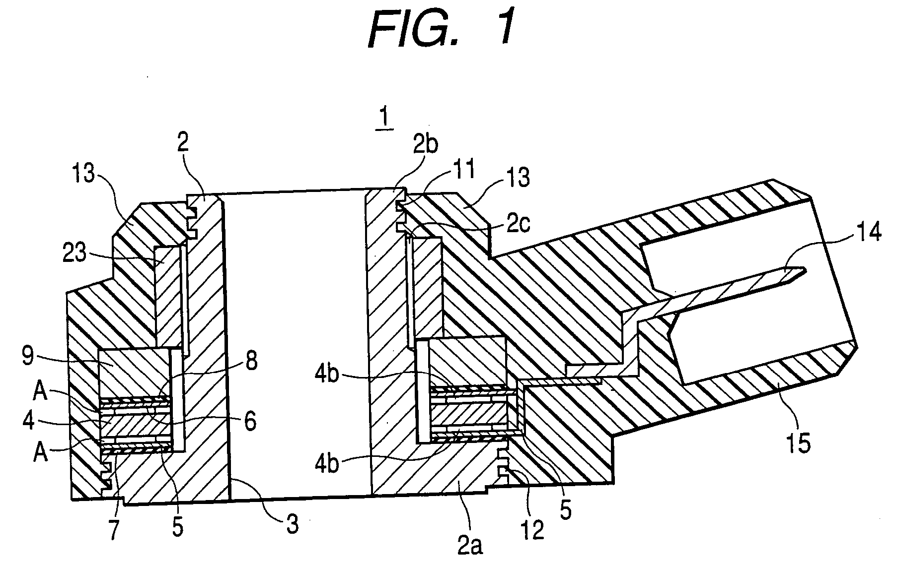
[0025]FIG. 1 is a sectional view showing an inner structure of a knock sensor of embodiment 1 of this invention.

[0026] The knock sensor 1 is constructed such that all component parts are covered with a case 13 made of synthetic resin (for example, nylon 66), and a connector part 15 for connection with a connector from an ignition timing control device (not shown) is formed on the case 13.

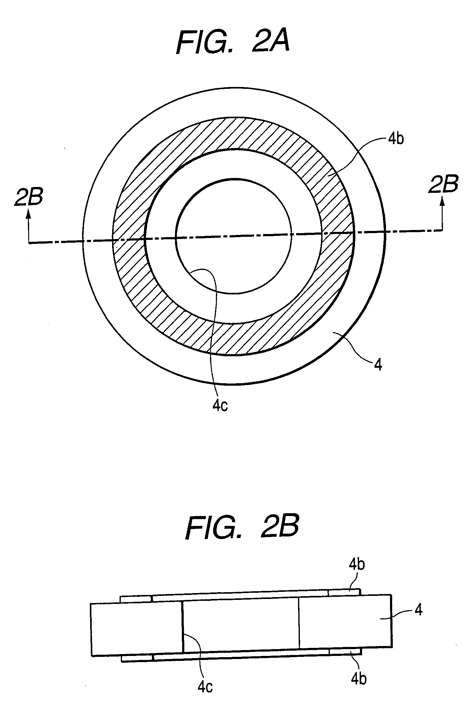
[0027] A base 2 is made of metal, and is constructed of a cylindrical part 2b having a through hole 3 and a disk-like flange part 2a provided at its one end. Plural engagement grooves 11 and 12 for ensuring engagement with the case 13 and preventing intrusion of water from the outside are formed on the outer peripheral surface of the flange part 2a and the tip end (upper end in the drawing) outer peripheral surface of the cylindrical part 2b. An annular piezoelectric element 4 is slid onto a portio...

embodiment 2

[0038] Next, embodiment 2 of this invention will be described with reference to the drawings.

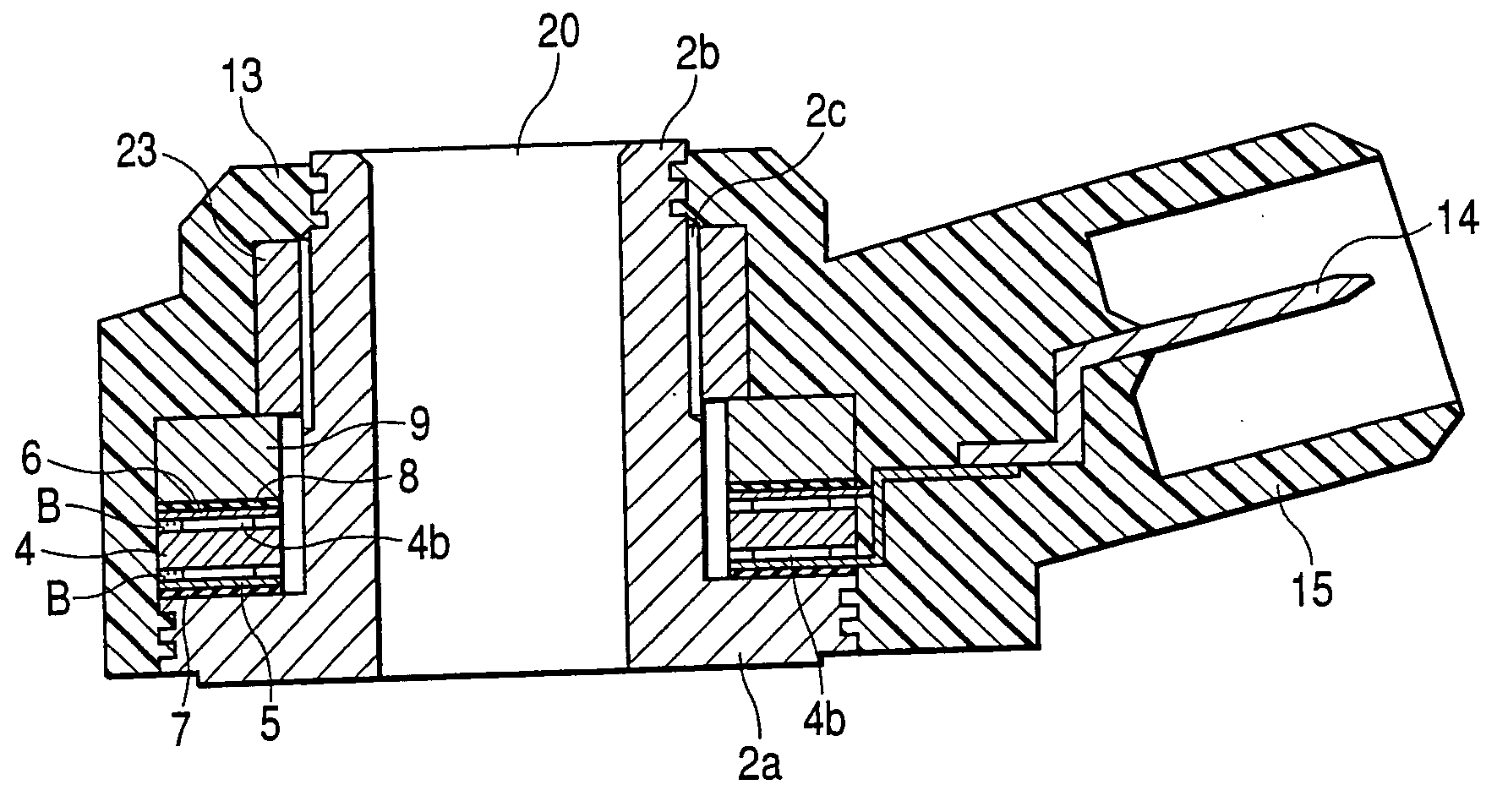
[0039]FIG. 3 is a sectional view showing an inner structure of a knock sensor 20 of embodiment 2 of the invention.

[0040] Although embodiment 2 has the same structure as embodiment 1, a conductive adhesive B is filled in a gap existing between an electrodeless part of an electrode formation surface of a piezoelectric element 4 and terminal plates 5 and 6 and corresponding to the thickness of a partial electrode 4b of the piezoelectric element 4. As the conductive adhesive B, an epoxy adhesive containing conductive metal powder is suitable.

[0041] In order to apply the conductive adhesive B to the electrode formation surface of the piezoelectric element 4, there is a method in which the piezoelectric element 4 is rotated under a discharge port of a dispenser for discharging a predetermined material, and a uniform coat is applied to a predetermined coated surface, or a method in which the pie...

embodiment 3

[0047] Next, embodiment 3 of this invention will be described with reference to the drawings. FIG. 4 is a sectional view showing a structure of embodiment 3. In a knock sensor of embodiment 3, a gap existing between an electrodeless part of an electrode formation surface of a piezoelectric element 4 and terminal plates 5 and 6 and corresponding to the thickness of a partial electrode 4b of the piezoelectric element 4 is filled with an electric insulating material C containing a filler having a particle size smaller than the gap. Since the other structure is the same as embodiment 1, its description will be omitted. As a manufacturing method, manufacture can be made by the same manufacturing method as embodiment 1. However, since the filler in the electric insulating material C is dispersed without being collapsed in the gap, the material can be filled in the gap without damaging the physical properties of the electric insulating material C.


PUM

PropertyMeasurementUnit
pressureaaaaaaaaaa
thicknessaaaaaaaaaa
weightaaaaaaaaaa

Abstract

A knock sensor of the invention includes a base having a cylindrical part mounted on a vibration generating part and a flange part, an annular piezoelectric element fitted to the cylindrical part and for converting a knocking vibration of the vibration generating part into an electric signal to detect it, electrodes respectively provided to be in contact with both surfaces of the piezoelectric element, terminal plates disposed to be in contact with the respective electrodes and for extracting an output of the piezoelectric element to outside, and a hold unit for pressure holding the piezoelectric element, the electrodes and the terminal plates to the flange part, in which the electrodes are provided to be in partial contact with the piezoelectric element, and an electric insulating material having an almost equal thickness to the electrode is provided on a portion of the piezoelectric element which is not in contact with the electrode.

Description

BACKGROUND OF THE INVENTION [0001] 1. Field of the Invention [0002] The present invention relates to a knock sensor and particularly to a nonresonant knock sensor mounted on, for example, a vibration generating part of an internal combustion engine or the like and for converting a knocking vibration of the internal combustion engine into an electric signal to detect it. [0003] 2. Description of the Related Art [0004] A structure of a conventional knock sensor will be described with reference to the drawings. FIG. 8 is a sectional view showing an inner structure of a generally known knock sensor 70. A metal base 21 mounted on a vibration generating part of an internal combustion engine or the like by a bolt or the like is constructed of a cylindrical part 21b in which a bolt through hole 22 is formed and a disk-like flange part 21a formed at its end. A lower insulating sheet 7 is slid onto the cylindrical part 21b to come in contact with the flange part 21a, and the following are suc...

Claims


Application Information

Patent Timeline
Patent Type & Authority Applications(United States)
IPC IPC(8): G01H17/00F02D35/00G01H11/08G01L23/10G01L23/22G01P15/09
CPCG01P15/0907G01L23/10G01L23/22
Inventor SHIBATA, HARUMASAYOKOI, AKITOMIYAKE, KEIZOINABA, HIDEHIRO
Owner MITSUBISHI ELECTRIC CORP
Why Eureka
Try Eureka