Heat dissipation device and manufacturing method thereof

a heat dissipation device and manufacturing method technology, applied in semiconductor devices, semiconductor/solid-state device details, cooling/ventilation/heating modifications, etc., can solve the problems of not dissipating heat sufficiently, not meeting the heat generating rate of high-power chips, and components that are at risk of damage, etc., to reduce the total weight of components, reduce costs, and improve heat dissipation efficiency

Inactive Publication Date: 2005-10-20
VIA TECH INC
View PDF11 Cites 11 Cited by
  • Summary
  • Abstract
  • Description
  • Claims
  • Application Information

AI Technical Summary

Benefits of technology

[0010] The present invention provides a heat dissipation device and manufacturing method thereof, which particularly reduces the total weight thereof and provides good thermal conductivity for reducing costs and increasing efficiency.

Problems solved by technology

Without proper heat dissipation, the components run the risk of damage, even to the point of interrupting the host.
This method is most economical; however, the thickness of the fins and the spacings therebetween are wider, such that it usually does not meet the heat generating rate of a high-power chip, and does not dissipate heat sufficiently.
Although this method increases the number of fins and thus the heat dissipation area of the heat dissipation device, the conductive efficiency between the base board and the fins is also limited because the base board and the fins are not connected directly.
The operation of the chip is possibly interrupted because the heat can not be dissipated efficiently.
However, the fins are arranged too tightly, and the narrow spacing between the fins of the above heat dissipation device causes other problems.
For example, the velocity of the air convention at the bottom of the spacing is low because the airflow turns, and results in dust being deposited on the bottom portion of the spacing.
The deposited dust will reduce the heat dissipation rate, and it is hard to remove because of the tight fins.
Further, the life-span of the heat dissipation device is shortened.

Method used


Image

  • Heat dissipation device and manufacturing method thereof
  • Heat dissipation device and manufacturing method thereof
  • Heat dissipation device and manufacturing method thereof

Examples


first embodiment

[0029] Reference is made to FIG. 7, which illustrates a perspective view of the heat dissipation device of first embodiment according to the present invention, By the above-mentioned steps, a heat dissipation device 100 according to the present invention is shown. The heat dissipation device 100 has a thermal conductive portion 3 and a plurality of fins 2 which are integrally formed with the thermal conductive portion 3. Each of the fins 2 has a plurality of through holes 20, a top portion 22 and a bottom portion 24. The through holes 20 are long and parallel to each other, and are formed from the channels 10 during skiving processes.

[0030] Each of the bottom portions 24 extends in a curve from the thermal conductive portion 3 and perpendicular to the thermal conductive portion 3. The through holes 20 of the fins 2 not only reduce the total weight, but also enhance air convention and lateral air can therefore flow through the heat dissipation device 100, especially for the inner fin...

second embodiment

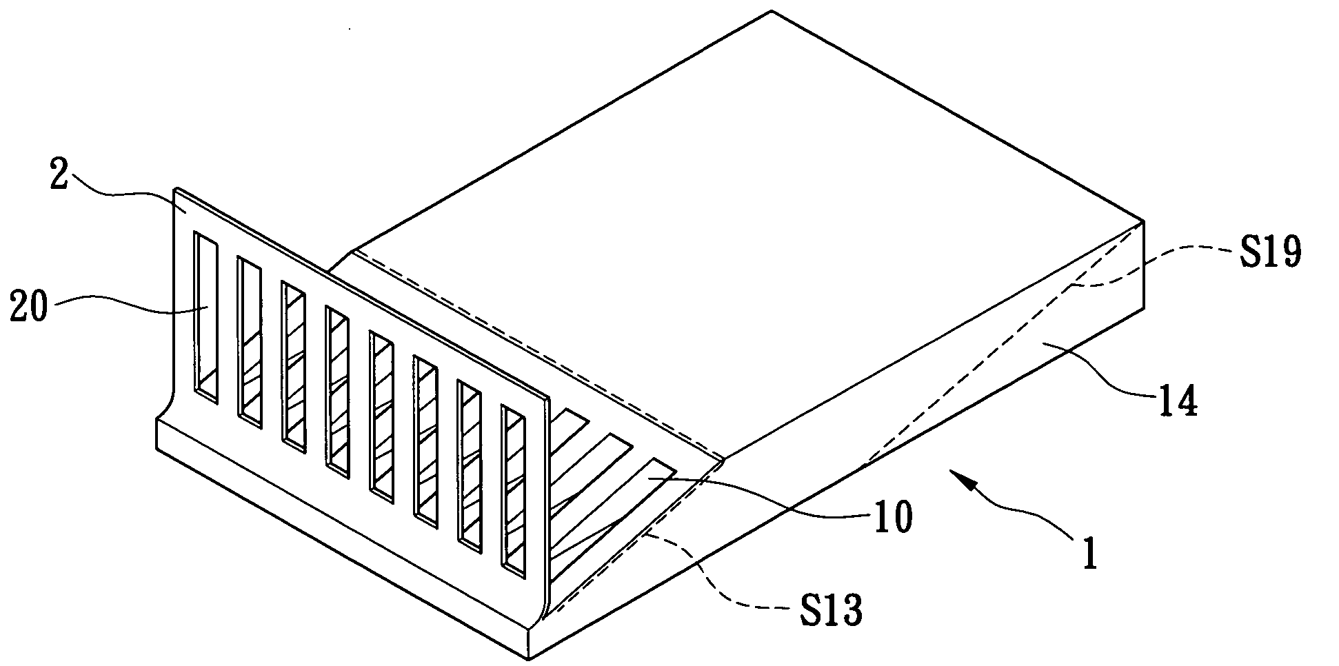
[0032] Referring to FIGS. 8 to 10, a heat dissipation device and manufacturing method thereof of another embodiment according to the present invention is illustrated. A metal board 1a has a base portion, which is formed integrally with a first base portion 11a and a second base portion 13a with different heights during extruding. The metal board 1a is skived along the line S21 with the predetermined oblique angle in FIG. 4. The line S21 is skived to bottom edges of channels 10a. It can be skived to above the bottom edges of the channels 10a. Referring to FIG. 8, then a metal slice is then skived along a line S22, which is parallel to the line S21, and the metal slice is erected to form the fins 2a as illustrated in FIG. 9. The above step of skiving the metal slice is repeated until a last metal block 14a is cut off, and a heat dissipation device 200 of second embodiment according the present invention is shown in FIG. 10.

[0033] Referring to FIG. 10, the heat dissipation device 200 h...


PUM


Abstract

A heat dissipation device is made by skived-fin technology and has a thermal conductive portion and a plurality of fins. The fins are integrally formed with the thermal conductive portion. Each of the fins has a plurality of through holes, a top portion, and a bottom portion. The bottom portion of each fin connects with the thermal conductive portion with a curve. The thermal conductive portion, which is disposed on the bottom of the heat dissipation device, is integrally formed with the fins in one metal board.

Description

BACKGROUND OF THE INVENTION [0001] 1. Field of the Invention [0002] The present invention relates to a heat dissipation device and a manufacturing method thereof, and particularly to a heat dissipation device and a manufacturing method thereof using skived-fin technology for thermal dissipation of high-power chip. [0003] 2. Description of Prior Art [0004] As the density of an IC (integrated circuit) increases, the chip of information product produces more heat, and the temperature of the chip is usually over the maximum temperature limit. In particular, the operating speed and the processing function of the CPU (central processing unit) are increasing continually. Without proper heat dissipation, the components run the risk of damage, even to the point of interrupting the host. [0005] To solve the heat dissipation problem of the chip, a heat dissipation device with multiple fins is usually mounted on the chip. The conventional art is shown in FIG. 1. A heat dissipation device 9 has ...

Claims


Application Information

Patent Timeline
Patent Type & Authority Applications(United States)
IPC IPC(8): H01L23/367H01L23/467H05K7/20
CPCH01L23/3672H01L23/467F28F3/048H01L2924/0002H01L2924/00
Inventor LIN, JUNG-AN
Owner VIA TECH INC
Why Eureka
Try Eureka