
Automatic takeoff apparatus for aircraft, automatic landing apparatus for aircraft, automatic takeoff and landing apparatus for aircraft, automatic takeoff method for aircraft, automatic landing method for aircraft and automatic takeoff and landing method for aircraft

a technology for aircraft and landing apparatus, which is applied in the direction of aircraft navigation control, automatic actuation, instruments, etc., can solve the problems of complicated structure of loaded apparatuses and difficulty in landing under full automatic control

Inactive Publication Date: 2005-10-20
SUBARU CORP
View PDF17 Cites 22 Cited by
  • Summary
  • Abstract
  • Description
  • Claims
  • Application Information

AI Technical Summary

Benefits of technology

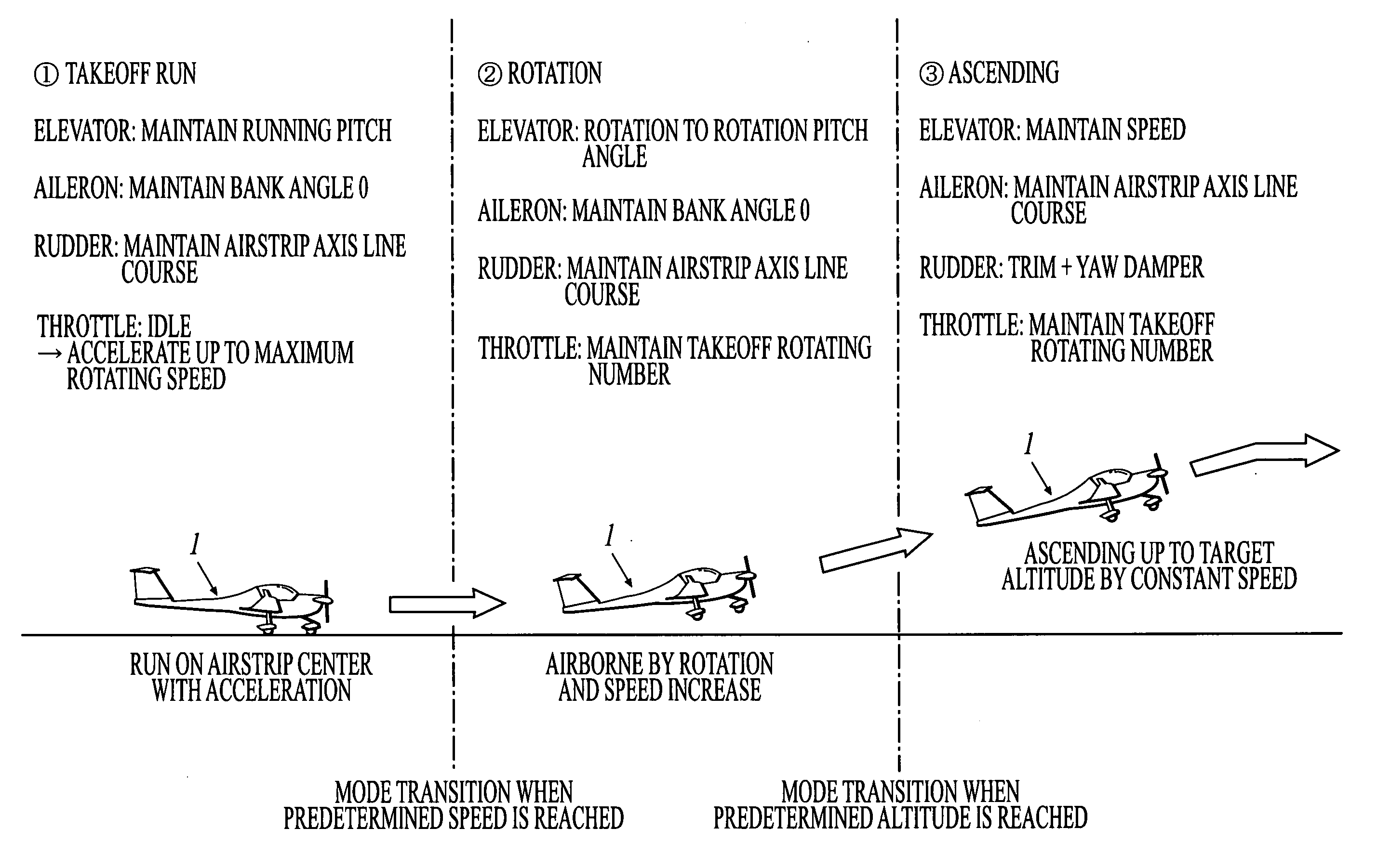
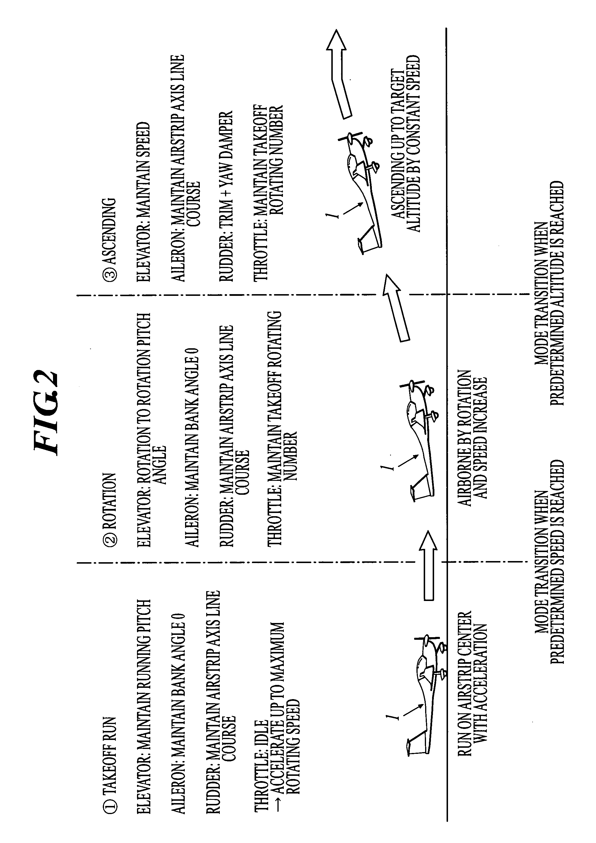
The present invention provides an automatic takeoff and landing apparatus for aircraft that can achieve full automatic takeoff and landing without using complicated loaded apparatus or control logic. The control device includes a takeoff command inputting section, an altitude sensor, an airspeed sensor, an attitude angle sensor, a direction sensor, a takeoff command inputting section, a control device, and a control section for takeoff, rotation, ascending flight, flare, landing, and landing run. The control device controls the propulsion device and control surface of the aircraft based on the altitude, airspeed, attitude angle, direction, position, takeoff command, and landing command. The technical effect of the invention is to simplify the process of takeoff and landing for piloted aircraft, reducing the risk and complexity of the flight.

Problems solved by technology

Therefore, in reality, it was difficult to perform a landing under a full automatic control.
Since it is necessary to provide landing gear switches as many as the number of feet, a structure of loaded apparatuses became complicated.
Further, since the landing gear switch easily malfunctions, it was necessary to establish a complicated control logic under an assumption of a case of malfunctioning.

Method used


Image

  • Automatic takeoff apparatus for aircraft, automatic landing apparatus for aircraft, automatic takeoff and landing apparatus for aircraft, automatic takeoff method for aircraft, automatic landing method for aircraft and automatic takeoff and landing method for aircraft
  • Automatic takeoff apparatus for aircraft, automatic landing apparatus for aircraft, automatic takeoff and landing apparatus for aircraft, automatic takeoff method for aircraft, automatic landing method for aircraft and automatic takeoff and landing method for aircraft
  • Automatic takeoff apparatus for aircraft, automatic landing apparatus for aircraft, automatic takeoff and landing apparatus for aircraft, automatic takeoff method for aircraft, automatic landing method for aircraft and automatic takeoff and landing method for aircraft

Examples


Embodiment Construction

[0030] Hereinafter, an embodiment of the present invention will be described with reference to drawings.

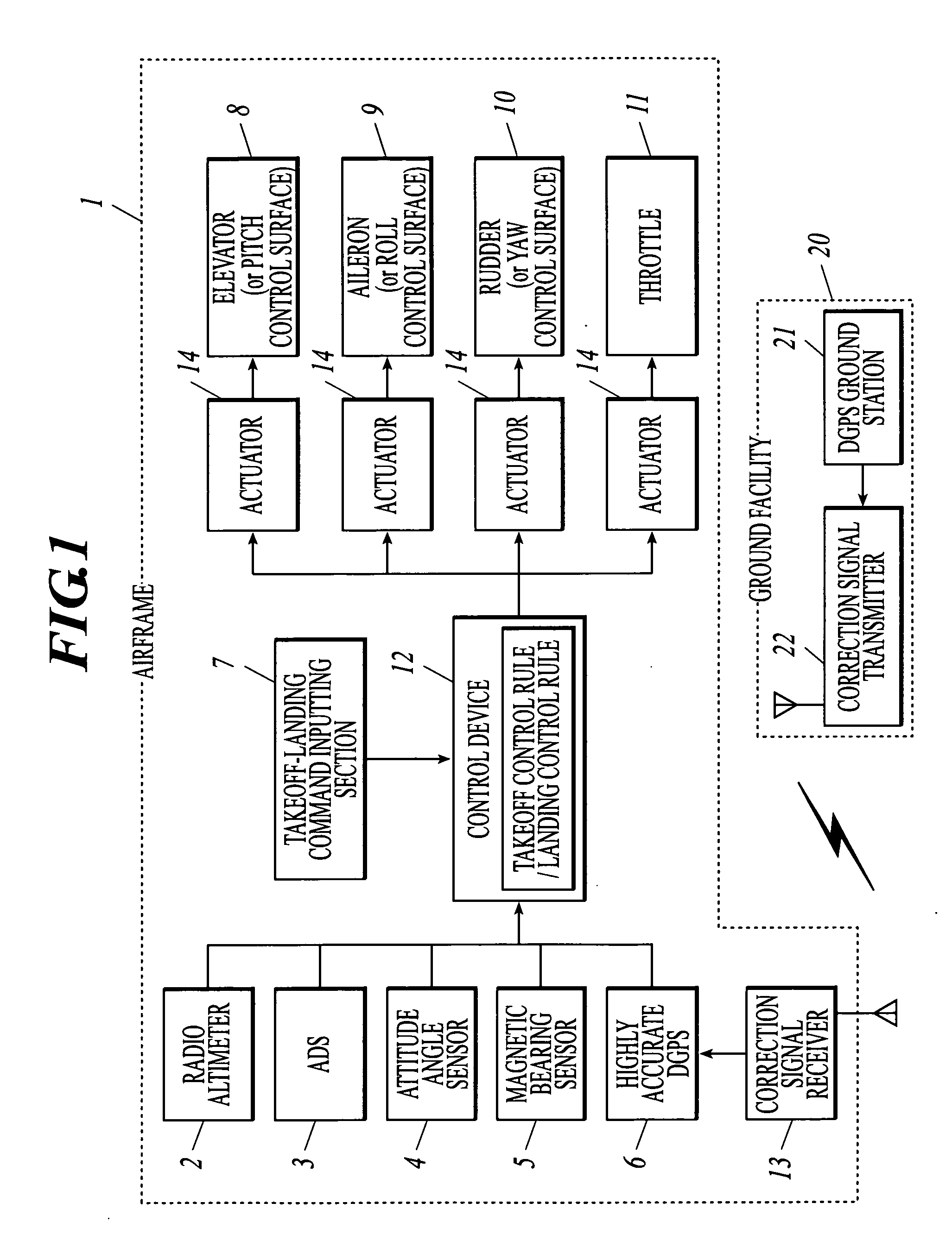
[0031] First, with reference to FIG. 1 to FIG. 8, a structure of an automatic takeoff and landing apparatus relating to the present embodiment will be described. Here, the automatic takeoff and landing apparatus relating to the present embodiment is to realize a full automatic takeoff and landing of a fixed wing aircraft (hereafter, it is referred to as “aircraft”) 1.

[0032] As shown in FIG. 1, the automatic takeoff and landing apparatus comprises a radio altimeter 2, an ADS (Air Data Sensor) 3, an attitude angle sensor 4, a magnetic bearing sensor 5, a highly accurate DGPS (Differential Global Positioning System) 6, a takeoff-landing command inputting section 7, control surface (an elevator 8, an aileron 9 and a rudder 10), a throttle 11, a control device 12, a ground facility 20 and the like.

[0033] The radio altimeter 2 is an altitude sensor in the present invention. The radio...


PUM


Abstract

An automatic takeoff apparatus for an aircraft includes: an altitude sensor; an airspeed sensor; an attitude angle sensor; a direction sensor; a takeoff command inputting section; and a control device for controlling a propulsion device and an control surface of the aircraft, wherein the control device includes: a takeoff run control section for realizing a takeoff run by controlling the propulsion device to provide a maximum output and by controlling the control surface to maintain the attitude angle and the traveling direction constant, in response to the takeoff command; a rotation control section for controlling the control surface to rotate when the airspeed exceeds a predetermined speed; and an ascending flight control section for controlling the propulsion device and the control surface to perform an ascending flight up to a target altitude with a predetermined speed maintained, when the altitude exceeds a predetermined altitude.

Description

CROSS-REFERENCE TO RELATED APPLICATIONS [0001] The disclosure of Japanese Patent Application No. 2004-120814 filed on Apr. 15, 2005, including the specification, drawings and abstract is incorporated herein by reference in its entirety. BACKGROUND OF THE INVENTION [0002] 1. Field of the Invention [0003] The present invention relates to an automatic takeoff apparatus for an aircraft, an automatic landing apparatus for an aircraft, an automatic takeoff and landing apparatus for an aircraft, an automatic takeoff method for an aircraft, an automatic landing method for an aircraft and an automatic takeoff and landing method for an aircraft. [0004] 2. Description of Related Art [0005] So far, several technologies for realizing an automatic landing of an aircraft have been proposed. As shown in FIG. 9, what is proposed for example is an automatic landing apparatus (ILS: Instrument Landing System) for making an airframe approach and land on a predetermined airstrip 300 by transmitting a gui...

Claims


Application Information

Patent Timeline
Patent Type & Authority Applications(United States)
IPC IPC(8): B64C13/18B64D45/04G05D1/06G08G5/02
CPCG05D1/0653B64C13/18
Inventor YAMANE, AKIHIRO
Owner SUBARU CORP
Learn More