Vehicle seat frame

a seat frame and vehicle technology, applied in the field of vehicle seat frames, can solve the problems of frame failure, laborious and expensive frame fabrication and assembly, and the support of foam cushions may not be uniform, so as to reduce the center of gravity of the seat assembly, and the cost of manufacturing

Inactive Publication Date: 2005-10-20
SEARS MFG
View PDF12 Cites 20 Cited by
  • Summary
  • Abstract
  • Description
  • Claims
  • Application Information

AI Technical Summary

Benefits of technology

[0004] The present invention overcomes the disadvantages of the prior art by providing a one piece, magnesium die cast seat frame. The seat frame of the present invention utilizes a unique die cast design that is strong, durable and yet relatively inexpensive to manufacture. In accordance with the present invention, the seat frame comprises a unitary body having a top, a bottom, two sides, and front and back surfaces. The front surface has an outer perimeter flange positioned adjacent the two sides and the top of the body. An inner perimeter flange is spaced from and generally coextensive with the outer perimeter flange. The front surface also has at least one generally horizontally oriented flange and at least two generally diagonally oriented flanges. This arrangement, together with the use of the die cast magnesium, results in a lightweight yet strong and durable frame that provides generally uniform support to the overlying seat cushion. The frame body is also provided with a large aperture that is positioned to desirably lower the seat assembly center of gravity.

Problems solved by technology

Most conventional truck seats are made using a metal tube frame, and frame failure is a common problem.
In addition to mechanical failure, the fabrication and assembly of the frame, when constructed from either sheet metal or tubing, can be labor intensive and expensive.
Another problem associated with these conventional frame designs is that the support for the foam cushion may not be uniform.
Plastic frames, however, are generally too flexible or not sufficiently robust and durable for the rigorous vehicle seat environment.
Some off the road vehicle seats have been made using die cast zinc frames, but these are relatively brittle and require an excessive amount of material to achieve satisfactory load bearing requirements.

Method used


Image

  • Vehicle seat frame
  • Vehicle seat frame
  • Vehicle seat frame

Examples


Embodiment Construction

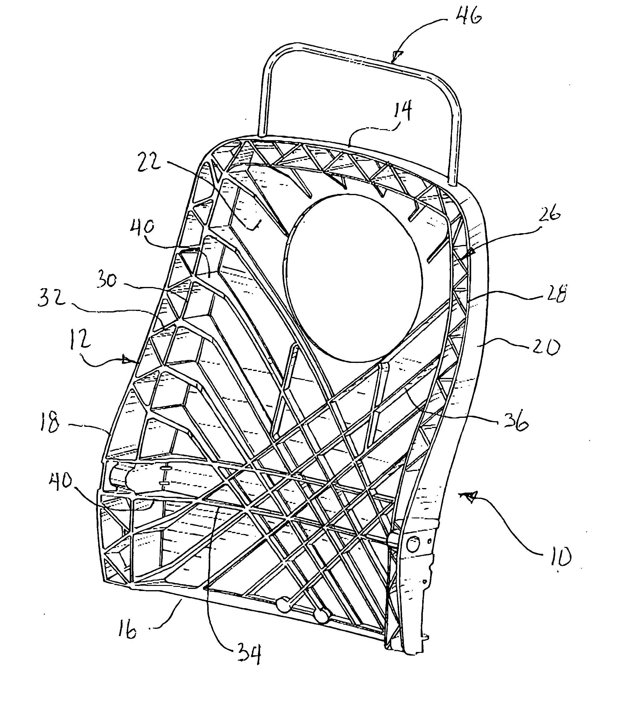
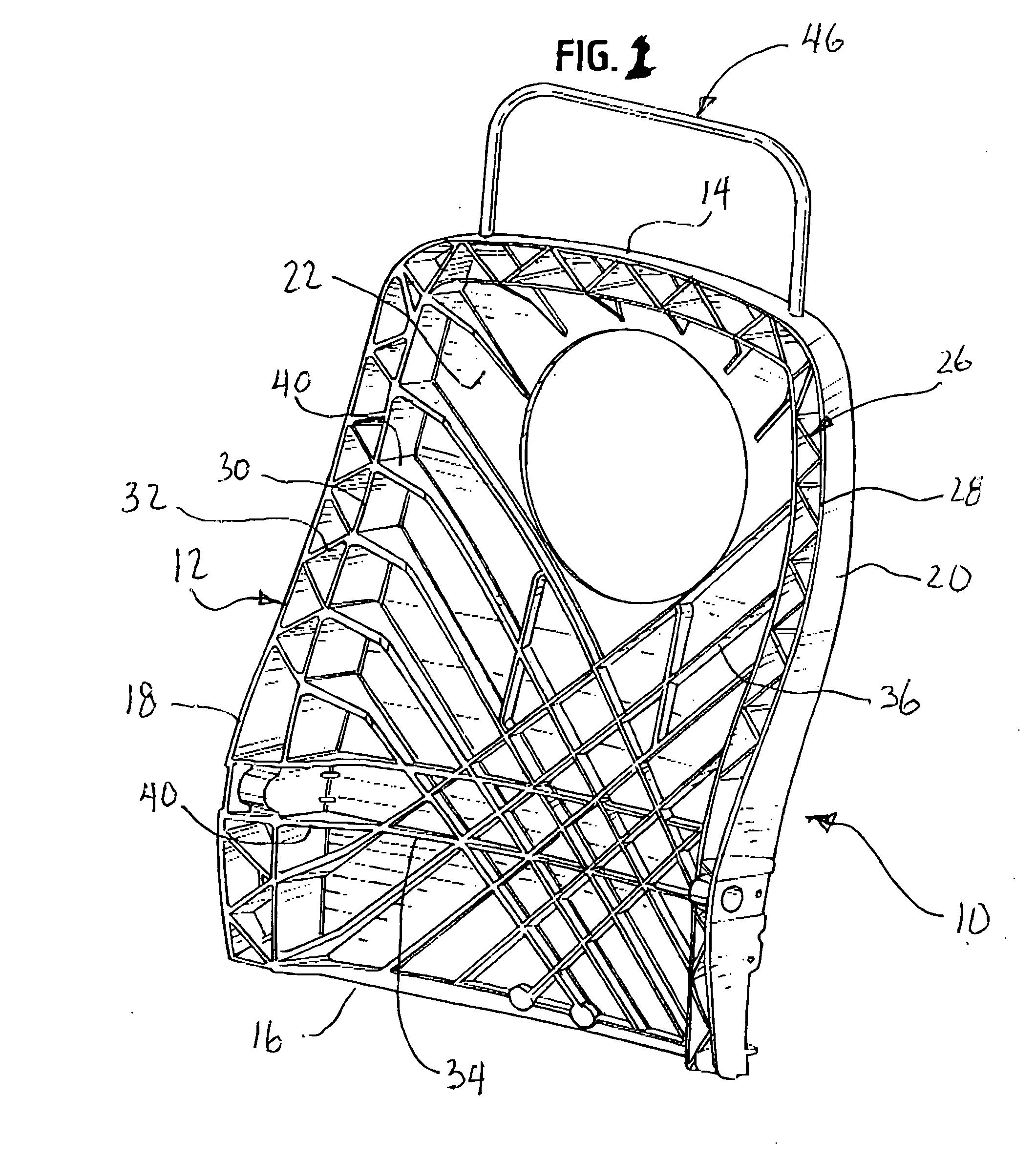
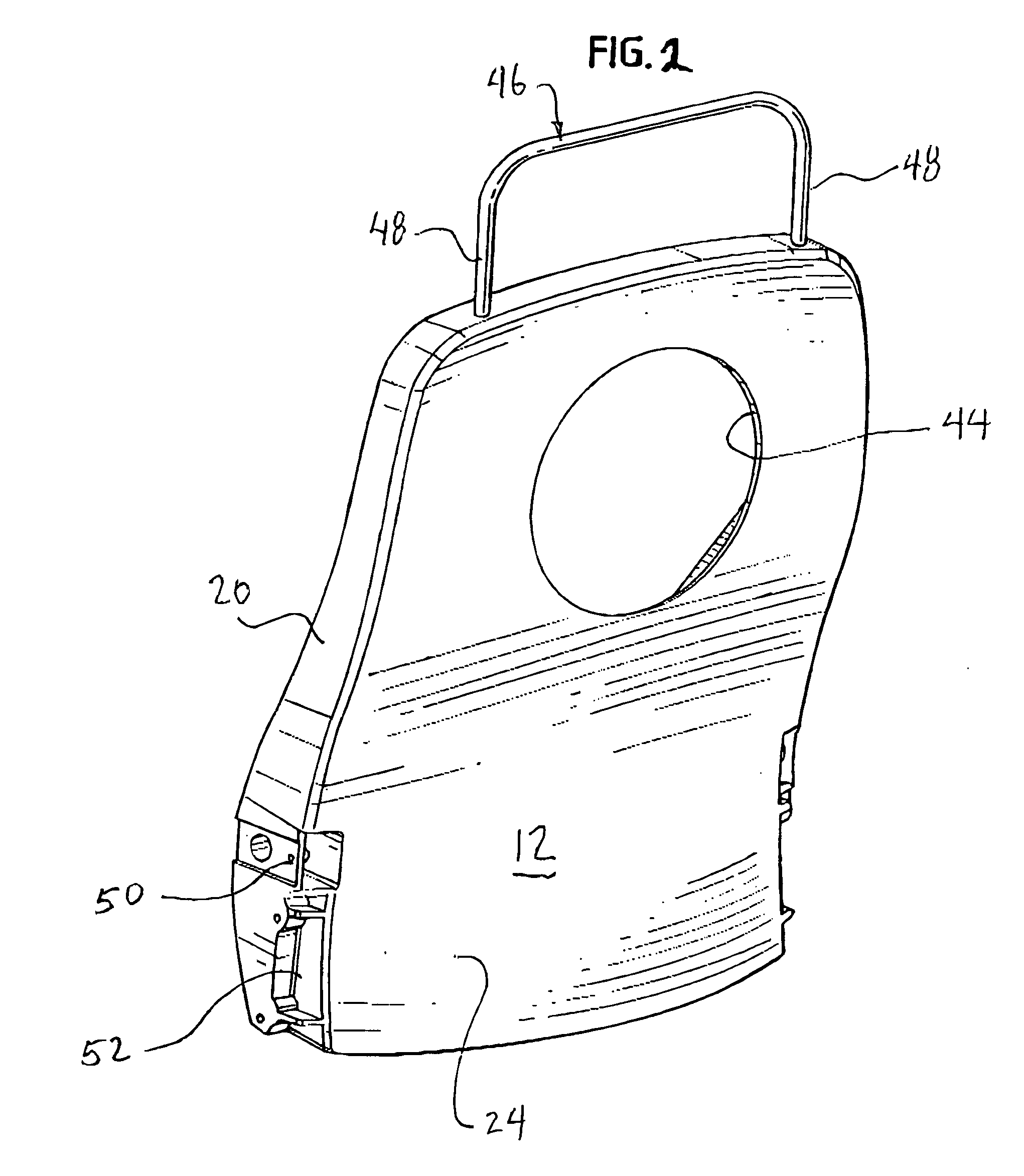
[0009] With reference to the drawings, one preferred embodiment of a vehicle seat frame constructed in accordance with the present invention is designated generally by reference numeral 10. Seat frame 10 is comprised of a body 12 having a top 14, a bottom 16, and two sides 18 and 20. The body 12 also has a front surface 22 and a back surface 24.

[0010] A perimeter rib 26 extends along the two sides and across the top of the body. Preferably, the rib 26 comprises an outer perimeter flange 28 and an inner perimeter flange 30, the two perimeter flanges protruding from the front surface of the body and separated from one another. A series of bridge flanges 32 extend between the two perimeter flanges, preferably arranged at an angle to the perimeter flanges. At least one and preferably two generally horizontal flanges 34 extend from the front surface of body 12, each positioned in the lower region of the body and preferably in the lumbar area of a seat occupant. A series of diagonally or...


PUM


Abstract

A seat frame comprises a unitary magnesium die cast body having a top, a bottom, two sides, and front and back surfaces. The front surface has an outer perimeter flange positioned adjacent the two sides and the top of the body. An inner perimeter flange is spaced from and generally coextensive with the outer perimeter flange. The front surface also has at least one generally horizontally oriented flange and at least two generally diagonally oriented flanges. This arrangement, together with the use of the die cast magnesium, results in a lightweight yet strong and durable frame that provides generally uniform support to the overlying seat cushion. The frame body is also provided with a large aperture that is positioned to desirably lower the seat assembly center of gravity.

Description

BACKGROUNG OF THE INVENTION [0001] The present invention relates generally to vehicle seating and, more particularly, to an improved vehicle seat frame designed primarily for over the road truck seating. [0002] Vehicle seating, such as that used in cars and trucks, typically includes an internal frame constructed from metal sheet stock or tubing. A foam cushion, with either a separate or integral upholstered cover, is assembled onto or molded over the frame. Most conventional truck seats are made using a metal tube frame, and frame failure is a common problem. In addition to mechanical failure, the fabrication and assembly of the frame, when constructed from either sheet metal or tubing, can be labor intensive and expensive. Another problem associated with these conventional frame designs is that the support for the foam cushion may not be uniform. [0003] These problems can be avoided to some extent by using a one piece frame; one, for example, made by injection molding a plastic fr...

Claims


Application Information

Patent Timeline
Patent Type & Authority Applications(United States)
IPC IPC(8): A47C7/40A47C27/00B60N2/68B60N2/90
CPCB60N2/686A47C7/40
Inventor GRYP, DENNIS
Owner SEARS MFG
Why Eureka
Try Eureka