Capacitive load driving circuit, droplet ejection device, droplet ejection unit and inkjet head driving circuit
a technology of inkjet head and driving circuit, which is applied in the direction of ac network voltage adjustment, printing, instruments, etc., can solve the problems of heat generation, poor power supply efficiency, and analog amplification circuits, so as to reduce the stability of operations
- Summary
- Abstract
- Description
- Claims
- Application Information
AI Technical Summary
Benefits of technology
Problems solved by technology
Method used
Image
Examples
first embodiment
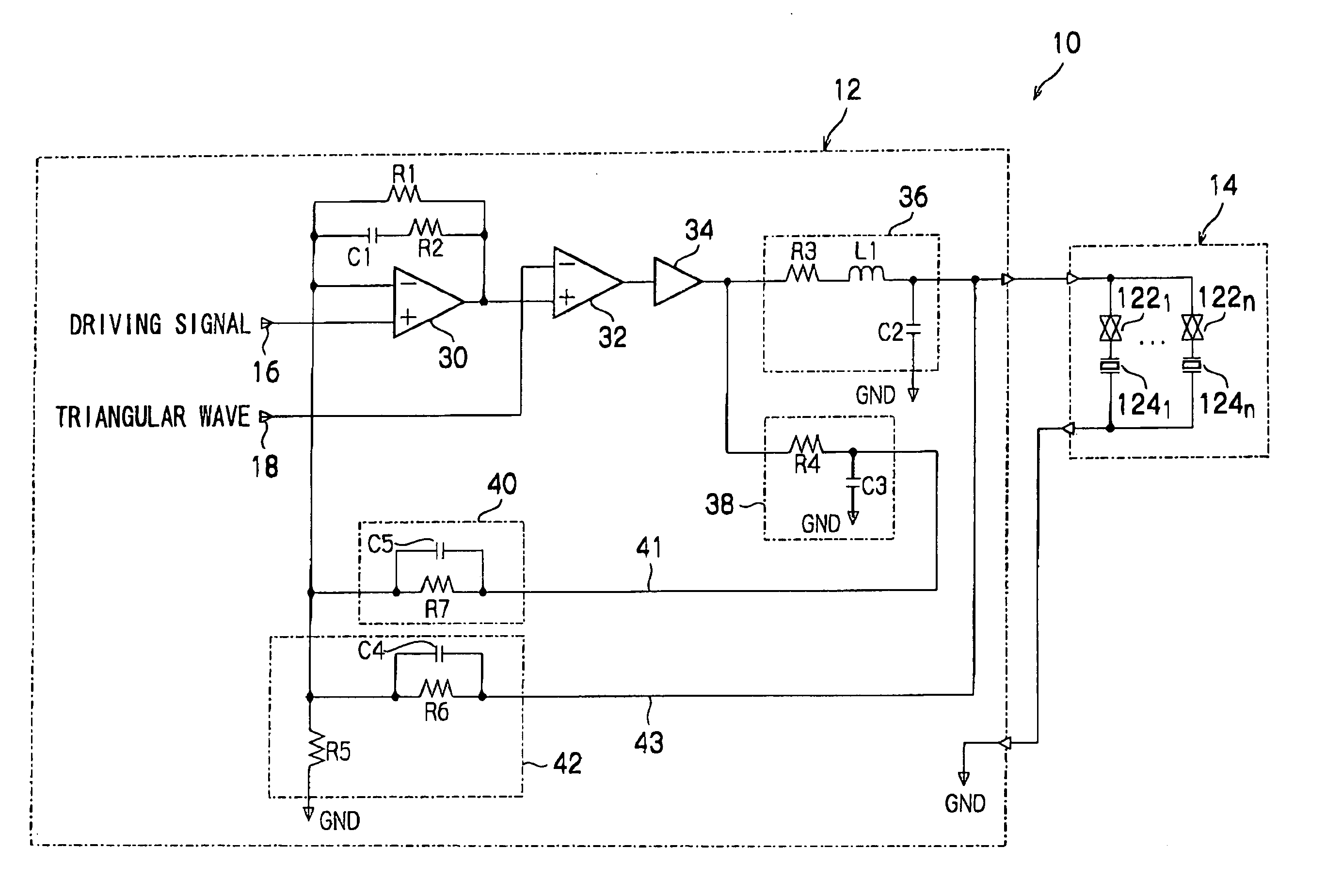
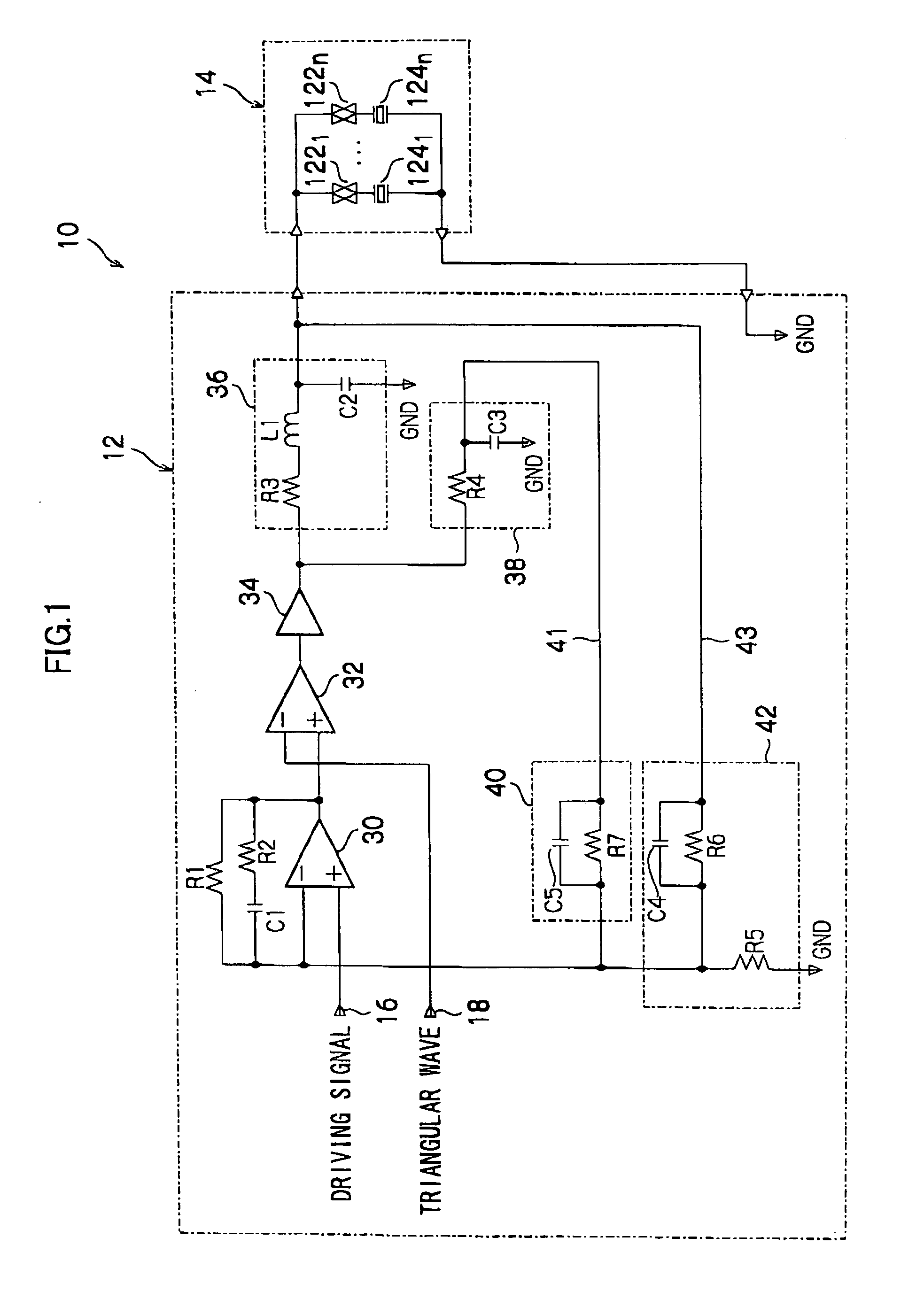
[0044] As shown in FIG. 1, an inkjet head driving circuit 10 of the present embodiment is structured with a driving circuit board 12 and a head 14. At the driving circuit board 12, an operational amplifier 30, a comparator 32, a digital power amplifier 34, a first filter 36, a second filter 38, a smoothing circuit 42 and a smoothing circuit 40 are formed. At the head 14, n (‘n’ being a natural number) transfer gates 1221 to 122n and n piezoelectric actuators 1241 to 124n, which are connected in respective series with the transfer gates 1221 to 122n, are provided.
[0045] A driving signal input terminal 16, at which an input signal is inputted, is connected to a non-inverting input terminal of the operational amplifier 30. An output terminal of the operational amplifier 30 is connected to a non-inverting input terminal of the comparator 32, which constitutes a pulse width modulator. The output terminal of the operational amplifier 30 is also connected to an inverting input terminal of...
second embodiment
[0123] For the first embodiment, the inkjet head driving circuit 10 shown in FIG. 1 has been described. In this inkjet head driving circuit 10, the output terminal of the first filter 36 is connected, via the first feedback circuit 43 including the smoothing circuit 42, to the inverting input terminal of the operational amplifier 30 and the output terminal of the digital power amplifier 34 is connected via the second feedback circuit 41, which includes the second filter 38 and the smoothing circuit 40 structured by the resistor R7 and the capacitor C5 connected in parallel with the resistor R7, to the inverting input terminal of the operational amplifier 30. For the second embodiment, a case which further includes a third feedback circuit, which feeds back output of the first filter 36 through a wiring resistance to the inverting input terminal of the operational amplifier 30, will be described.
[0124] If a wiring resistance R9 between the driving circuit board 12 and the head 14 as...
third embodiment
[0130]FIG. 8 is a circuit diagram showing an inkjet head driving circuit 10A relating to the third embodiment. The inkjet head driving circuit 10A of the third embodiment is a circuit in which the second filter 38 is removed from the inkjet head driving circuit 10 shown in FIG. 1 and a first filter 36A is provided instead of the first filter 36. In FIG. 8, circuits that are the same as circuits shown in FIG. 1 are assigned the same reference numerals, and detailed descriptions thereof are omitted.
[0131] The first filter 36A is provided with the inductor L1, the resistor R3 and the capacitor C2. One terminal of the inductor L1 is connected to the output terminal of the digital power amplifier 34 and the other terminal of the inductor L1 is connected to the resistor R3. Another terminal of the resistor R3 (the terminal thereof that is not connected to the inductor L1) is connected to the capacitor C2 and the transfer gates 1221 to 122n of the head 14. Another terminal of the capacito...
PUM
 Abstract
Description
Claims
Application Information
 - R&D
- Intellectual Property
- Life Sciences
- Materials
- Tech Scout
- Unparalleled Data Quality
- Higher Quality Content
- 60% Fewer Hallucinations
Browse by: Latest US Patents, China's latest patents, Technical Efficacy Thesaurus, Application Domain, Technology Topic, Popular Technical Reports.
© 2025 PatSnap. All rights reserved.Legal|Privacy policy|Modern Slavery Act Transparency Statement|Sitemap|About US| Contact US: help@patsnap.com


