Terminal of IC test fixture

Inactive Publication Date: 2005-10-20
SPEED TECH
View PDF4 Cites 0 Cited by
  • Summary
  • Abstract
  • Description
  • Claims
  • Application Information

AI Technical Summary

Benefits of technology

[0006] It is a primary object of the invention to provide a terminal of IC test fixture having

Problems solved by technology

It is not easy to make the pitch larger between the terminals, electrical current

Method used


Image

  • Terminal of IC test fixture
  • Terminal of IC test fixture
  • Terminal of IC test fixture

Examples


Embodiment Construction

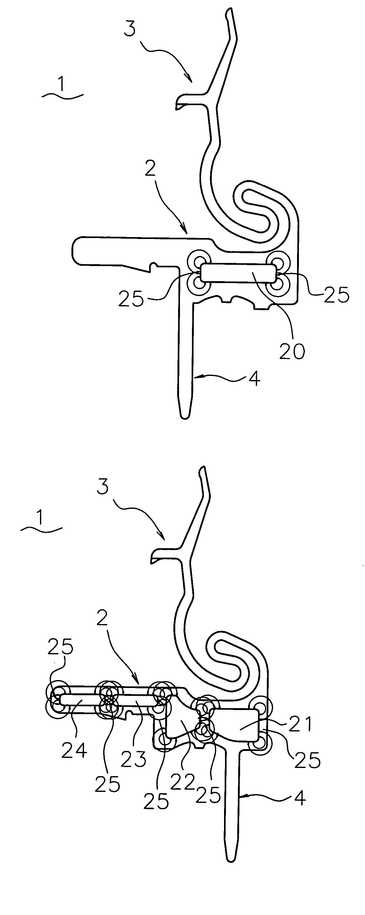
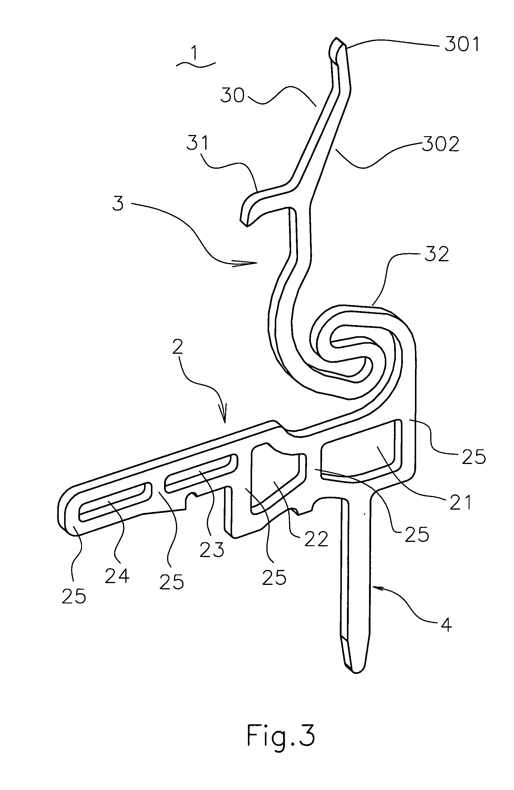
[0017] Referring to FIG. 4, the terminal 1 of the present invention, was made of a metal plate, comprises a body 2, a spring contact arm 3 and a soldering portion 4. There is at least one hollow holes 20 at the body 2 of the terminal 1, for forming at least two conductive paths 25 on it, making the electrical current flow subdivided.

[0018] An embodiment shown in FIG. 4, after the terminal 1 is installed in the IC test fixture and test an IC, the current flows from spring contact arm 3 to body 2, soldering portion 4 and PCB, or reversed, when current travels through the conductive paths 25 of the body 2 of the terminal 1, electromagnetic fields are generated over the conductive paths 25.

[0019] Since the directions of the current flows are the same and the electromagnetic fields of the two adjacent conductive paths 25 are opposite to each other during the current traveling through the body 2 of terminal 1, two electromagnetic fields interfere each other and result the coefficient of...


PUM


Abstract

A terminal of IC test fixture comprising a body, a spring contact arm and a soldering portion and there are at least one hollow holes on the body of the terminal. During testing, the electronic charges flow on the terminals generate electromagnetic field at the direction perpendicular to the electrical current flow, and the electronic current flows, which are near, generates electromagnetic fields with different directions, by the compensation and interference of electromagnetic fields each other, making the electromagnetic interference reduced. To suppress the electronic interference, the aforesaid hollow holes subdivide said electronic current flow, and that helps to constrain the electromagnetic interference during testing. Therefore, this invention can minimize electromagnetic interference among terminals for higher efficiency in testing the high frequency transmission IC's.

Description

BACKGROUND OF THE INVENTION [0001] I. Field of the Invention [0002] This invention relates generally to a terminal of an IC, integrated circuit, test fixture and, more specifically, to a terminal of an IC test fixture having adequate contact force to tested IC pins, low electromagnetic interference, high transmission efficiency and low manufacturing cost, is applied on the test of high frequency transmission IC's. [0003] II. Description of the Prior Art [0004] Heretofore, it is known that the IC testing fixture 7, as shown in FIG. 1, consists of a cover 5, a basement 6 and a plurality of terminals 7. Referring to FIG. 2, the terminal 7 further consists of a spring contact portion 72, a body 71 and a soldering portion 73; the spring contact portion 72 presses a pin of the tested IC downwardly by elastically deformed. The body 71 of the terminal 7 is arranged at the bottom of the spring contact portion 72, holding the terminal 7 into the basement 6 of the IC test fixture, and the sold...

Claims


Application Information

Patent Timeline
IPC IPC(8): G01R1/04G01R31/02
CPCG01R1/0466
Inventor HUNG, TENG SHENG
Owner SPEED TECH
Why Eureka
Try Eureka