Optical contact unit and optical plug

Active Publication Date: 2005-10-20
CANARE ELECTRIC
View PDF6 Cites 43 Cited by
  • Summary
  • Abstract
  • Description
  • Claims
  • Application Information

AI Technical Summary

Benefits of technology

[0045] Effects to be obtained by the present invention are explained as follows.
[0046] That is, according to the first aspect of the present invention, the main body and the cable adaptor can be connected without forming a screwing part or carrying out molding. As a result, neither too much time nor high technique is required in order to connect the main body and the cable adaptor. Further, according to the first aspect of the present invention, processes for forming components of the cable adaptor and the main body, respectively, can be carried out independently and in p

Problems solved by technology

Such manufacturing processes prol

Method used


Image

  • Optical contact unit and optical plug
  • Optical contact unit and optical plug
  • Optical contact unit and optical plug

Examples


first embodiment

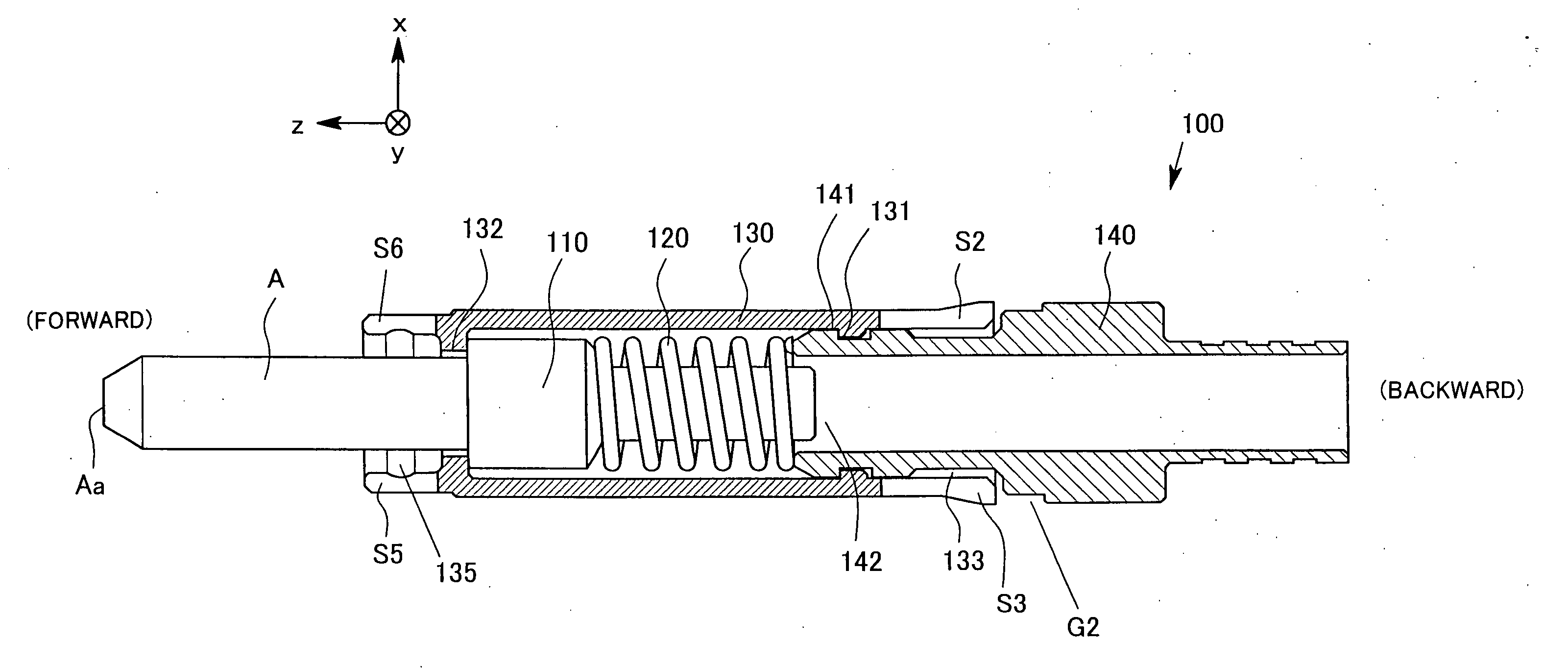
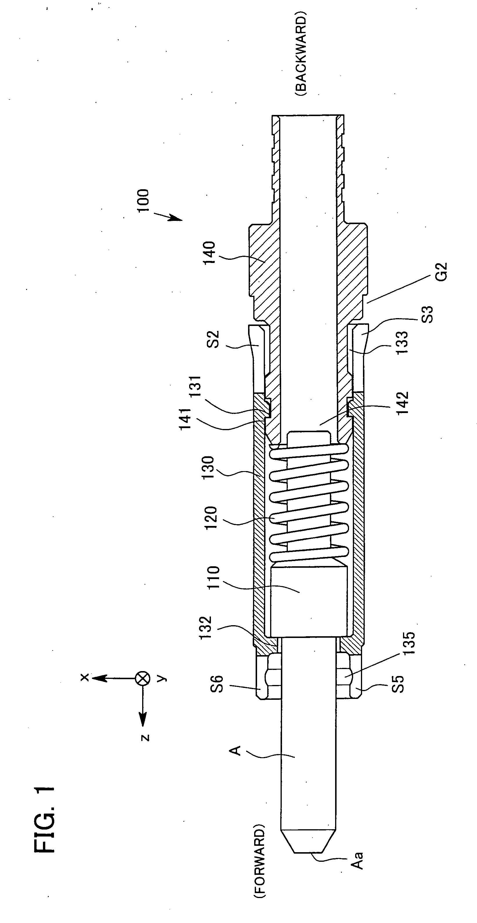
[0080]FIG. 1 is a sectional view of an optical contact unit 100 of an embodiment 1 in the present invention. A side view is shown with respect to a ferrule A, a ferrule holder 110, and a coil spring 120 (: elastic member). The optical contact unit 100 provides an elastic contact to face and automatically couples the ferrule A connected to the end part of an optical fiber on another ferrule B which is not illustrated in FIG. 1 and is placed at the front side of the ferrule A. Aa shown in FIG. 1 represents an end plane of the ferrule A, and that is a contact plane which contacts to the ferrule B.

[0081] The ferrule holder 110 and the coil spring 120 are comprised in a main body 130 formed in a tubular shape. A cable adaptor 140 comprising a large diameter part 141 and a front opening part 142 is inserted to the main body 130 from a back opening part 133 having slits S2 and S3. A first small diameter part 131 of the main body 130 binds with the large diameter part 141 of the cable adap...

second embodiment

[0105]FIGS. 6A and 6B illustrate a front view, a top view and a sectional view of an optical plug 4000 in the second embodiment of the present invention. The optical plug 4000 comprises the adaptor unit 1000 of the embodiment 1 described above. An agraffe 4400, a cramp body 4500, a pressure-bonding sleeve 4600, and a gum tube GT consist of a cable fixing part of the optical plug 4000. In the second embodiment, the central axis of an approximately cylindrical female plug shell 4100 is the z axis and the direction from the gum tube GT to an edge 4000a of the female plug 4000 is the positive direction of the z axis.

[0106] A slide sleeve 4150 formed in an approximately cylindrical shape is supported by a screw 4151 resiliently and guided to the z axis direction by a guide pin PN3, which enables to shuttle in the z axis direction in a predetermined range. Accordingly, a latching sleeve LS is pumped in the slide sleeve 4150 in diameter direction of the female plug shell 4100.

[0107] An i...

other modified embodiment

[0117] While the present invention has been described with reference to the above embodiments as the most practical and optimum ones, the present invention is not limited thereto, but may be modified as appropriate without departing from the spirit of the invention. By applying and modifying the embodiment, effect of the present invention can be obtained.


PUM


Abstract

A ferrule holder 110 and a coil spring 120 are comprised in a main body 130 formed in an approximately tube shape. A cable adaptor 140 comprising a front opening part 142 at a large diameter part 141 is inserted from a back opening part 133 into the main body 130 having slits S2 and S3. A first small diameter part 131 of the main body 130 fits with the large diameter part 141 of the cable adaptor 140 and prevents the cable adaptor 140 from translating in the z-axis direction. And the second small diameter part 132 of the main body 130 controls transfer of the ferrule holder 110 in the z-axis direction. At the forward part of the large diameter 141, a taper part which helps to insert the cable adaptor 140 is formed around the circuit of the optical axis. Each slit formed at the back opening part 133 also helps to insert the cable adaptor 140.

Description

TECHNICAL FIELD [0001] The present invention relates to an optical plug connecting optical fibers and mechanical structure of its contact. So the optical plug and the optical contact unit of the present invention are useful for a cable connector (coupler) comprising optical fibers. BACKGROUND ART [0002] Conventionally, as mechanical structure of a contact which connects optical fibers, the structure shown in a patent document 1, i.e., Japanese Patent Application Laid-open No. 2001-74977, is common and well-known. As disclosed in the patent document 1, problems persist in a conventional method for binding a male screw formed at a cable adaptor and female screw formed at a tube shape body by screwing them together. [0003] A conventional product in the patent document 1 is invented to solve this problem (referred to as a problem 0 hereinafter). As shown in the patent application 1, problems persist in the above-described junction structure because too much time and high technique are r...

Claims


Application Information

Patent Timeline
IPC IPC(8): G02B6/38
CPCG02B6/3821G02B6/3874G02B6/3825
Inventor TAKAHASHI, TETSUOKOMATSUBARA, MANABU
Owner CANARE ELECTRIC
Why Eureka
Try Eureka