Drainage grate

a technology of draining grate and grate, which is applied in the direction of paving gutter/kerb, sewer cleaning, agriculture, etc., can solve the problems of limiting the gauge of metal which can be used, being subject to damage, and being subject to pedestrian injury and damage to surface vehicles

Active Publication Date: 2005-10-20
ACO +1
View PDF11 Cites 9 Cited by
  • Summary
  • Abstract
  • Description
  • Claims
  • Application Information

AI Technical Summary

Benefits of technology

[0005] In accordance with the invention there is provided an improved drainage grate assembly which provides improved reinforcement and enables the use of varying gauges of sheet metal where other, more durable and costly materials such as cast iron might otherwise be required. Moreover, the instant invention is advantageously capable of providing substantially continuous support and reinforcement to the entire drainage grate. Accordingly, in one embodiment of the invention there is provided a reinforced drainage grate assembly comprising an elongate drainage grate and a reinforcing member disposed within the drainage grate. The drainage grate has a substantially planar drainage surface including a plurality of apertures there through and a pair of longitudinally extending side portions, each side portion extending orthogonally below the drainage surface and including a bottom flange extending toward the opposing one of said side portions. The reinforcing member is disposed between the bottom flanges and the underside of the drainage surface so that the upper surface of the reinforcing member abuts the underside of the drainage surface.

Problems solved by technology

Drainage grates are typically made of varying gauges of sheet metal and are, therefore, subject to damage.
Dents, buckles and perforations in the drainage grate are not only aesthetically undesirable, but are also safety concerns which can lead to injury to pedestrians and damage to surface vehicles.
However, there are practical limits to the gauges of metal which can be used and, even when various reinforcements are included, they do not provide continuous support to the entire drainage grate surface.
Thus, even a reinforced grate is still subject to damage in those regions which are not directly reinforced.

Method used


Image

  • Drainage grate
  • Drainage grate
  • Drainage grate

Examples


Embodiment Construction

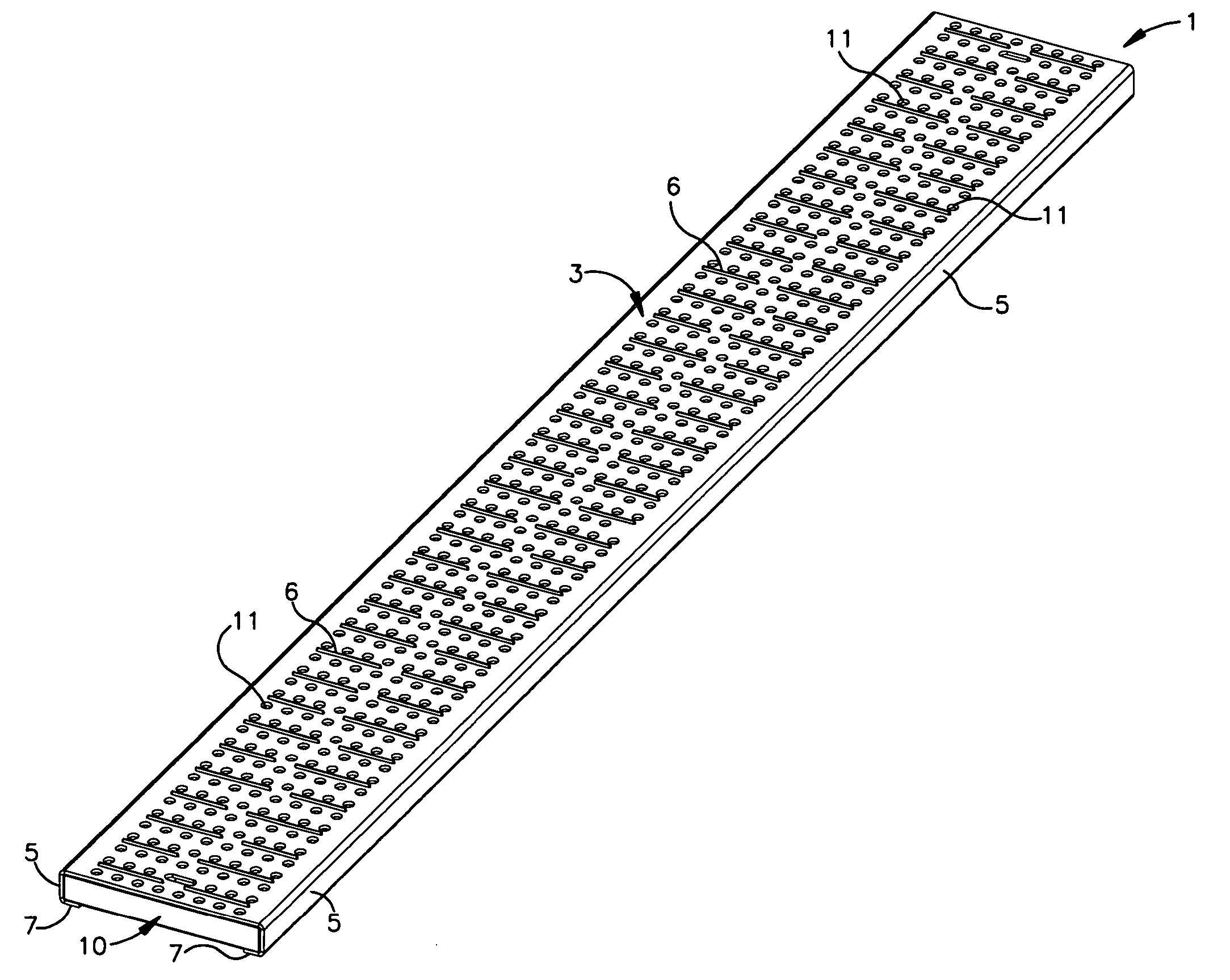
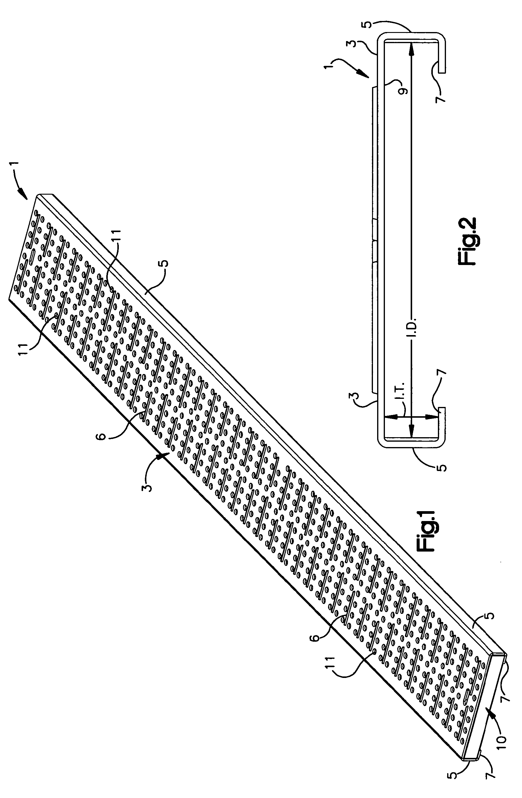
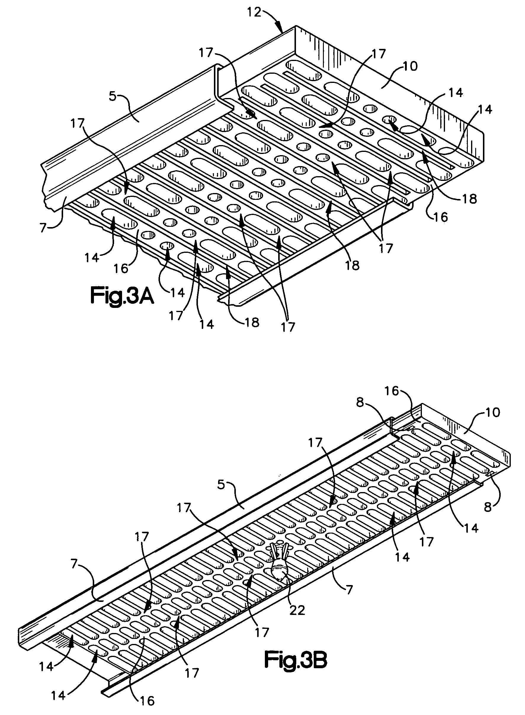
[0018] As seen with reference to the drawings, the preferred drainage grate assembly of the invention comprises an outer drainage grate, shown generally at 1, and an inner reinforcing member, shown generally at 10. As seen most clearly with reference to FIGS. 1 and 2, the drainage grate 1 is formed of sheet metal having a generally planar upper drainage surface 3, and a pair of opposed side portions 5 extending orthogonally below the drainage surface 3. In each case the side portions 5 include a lower flange portion 7 extending orthogonally, preferably perpendicularly, from the side portion toward the other of said side portions 5. As shown, the flange portions 7 extend continuously along the length of said side portions 5. However, as would be apparent to those of ordinary skill in the art in view of the instant disclosure, the flange portions 7 can be discontinuous, whereby a series of flange portions 7 can be disposed along the length of side portions 5, so long as they provide s...


PUM


Abstract

A drainage grate assembly having a drainage grate which is reinforced by a substantially continuous reinforcing member confined within the grate. The load rating for the drainage grate assembly can be adjusted by adding metal strips which can be disposed within and retained by the reinforcing member.

Description

BACKGROUND OF THE INVENTION [0001] The present invention relates to drainage grates used in connection with trench drains and the like for the drainage of surface water. Trench drains and similar drainage structures are used in a variety of environments, such as walkways, bike and foot paths, outdoor malls, parking lots, airport tarmacs and other traffic environments which require the drainage of surface water. Trench drains and drainage structures generally are known in the art as described in, for example, U.S. Pat. Nos. 4,630,966; 4,699,544; 5,462,382 and 4,553,874, incorporated herein by reference. In order to provide access of surface water to the drainage structure, while at the same time enabling practical movement of traffic across the structure, apertured drainage grates are typically employed to provide a substantially continuous surface over which pedestrian or vehicle traffic can freely move. [0002] Drainage grates are typically made of varying gauges of sheet metal and ...

Claims


Application Information

Patent Timeline
Patent Type & Authority Applications(United States)
IPC IPC(8): E01C11/22E02B11/00E03F5/06E04C2/42
CPCE03F5/06E04C2/427E03F2005/065
Inventor HUMPHRIES, DEREKHUMPAGE, ROYMAYO, GARY EDWIN
Owner ACO
Why Eureka
Try Eureka