Cap displacement mechanism for lancing device and multi-lancet cartridge

a technology of lancing device and cartridge, applied in the field of medical devices and procedures, can solve problems such as reducing the compliance with a prescribed test regimen

Active Publication Date: 2005-10-20
FACET TECH LLC
View PDF27 Cites 134 Cited by
  • Summary
  • Abstract
  • Description
  • Claims
  • Application Information

AI Technical Summary

Benefits of technology

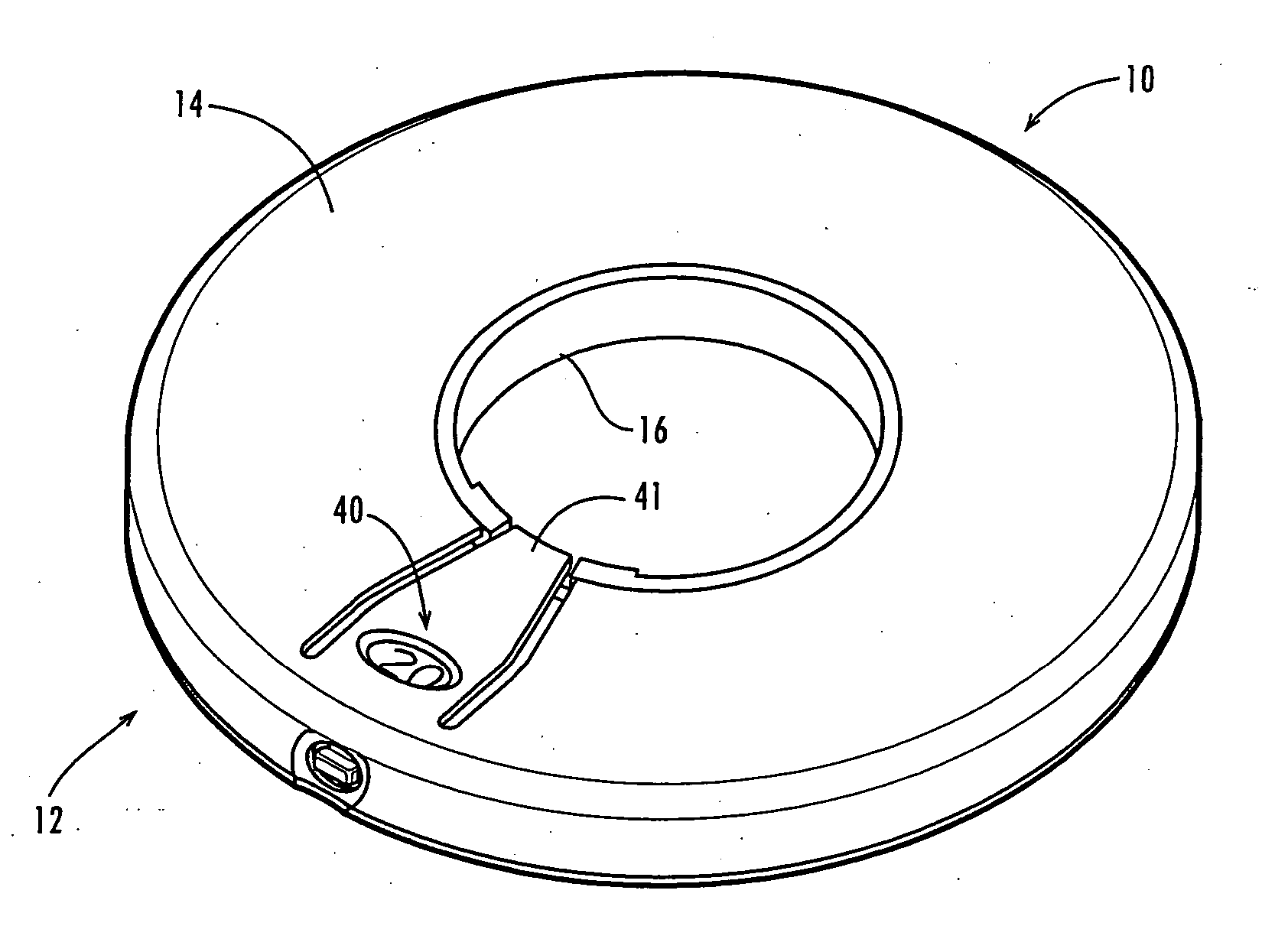
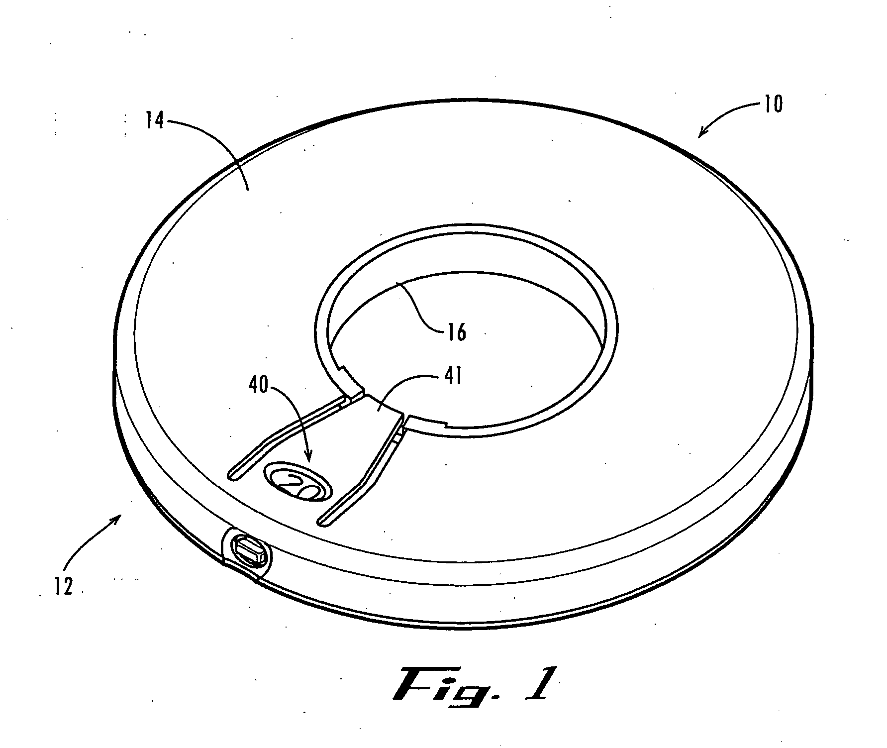
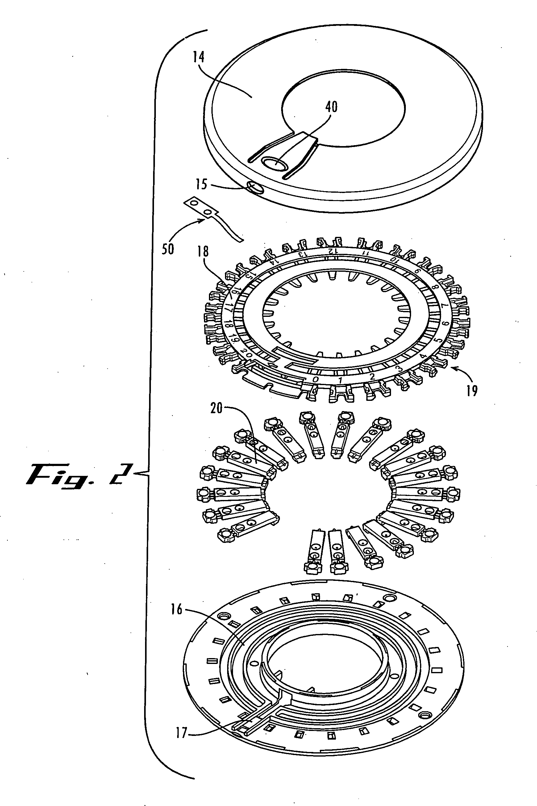
[0006] Briefly described, in one aspect, the present invention is a lancing device comprising an outer housing for receiving a replaceable cartridge. Preferably, the cartridge includes a static outer shell that remains stationary relative to the housing and drive mechanism of the lancing device, and an array of lancets that are rotationally advanced within the outer shell and sequentially indexed through an active position for carrying out multiple lancing procedures. The cartridge preferably includes a rotationally moveable carrier for retaining and rotationally advancing the radial array of lancets within the outer shell, and for constraining the active lancet along a controlled and pre-defined path of travel during the lancing stroke. The cartridge preferably also includes recesses, clips or other retainers for retaining protective endcaps that have been removed from the lancets out of the path of travel of the lancets, and preventing the caps from rattling around within the housing.

Problems solved by technology

Because re-use of a lancet can result in infection or spread of blood-borne contaminants, persons requiring repeated testing often must carry around multiple lancets that are separately loaded into a lancing device for each sampling.
This can be inconvenient and may lead to reduced compliance with a prescribed test regimen.

Method used


Image

  • Cap displacement mechanism for lancing device and multi-lancet cartridge
  • Cap displacement mechanism for lancing device and multi-lancet cartridge
  • Cap displacement mechanism for lancing device and multi-lancet cartridge

Examples


Embodiment Construction

[0029] The present invention may be understood more readily by reference to the following detailed description of the invention taken in connection with the accompanying drawing figures, which form a part of this disclosure. It is to be understood that this invention is not limited to the specific devices, methods, conditions or parameters described and / or shown herein, and that the terminology used herein is for the purpose of describing particular embodiments by way of example only and is not intended to be limiting of the claimed invention. Also, as used in the specification including the appended claims, the singular forms “a,”“an,” and “the” include the plural, and reference to a particular numerical value includes at least that particular value, unless the context clearly dictates otherwise. Ranges may be expressed herein as from “about” or “approximately” one particular value and / or to “about” or “approximately” another particular value. When such a range is expressed, anothe...


PUM


Abstract

A medical lancing device including a replaceable multi-lancet cartridge. The lancing device includes an advancing mechanism that advances lancets within the cartridge into an active position, separates a protective cap from the active lancet, and energize a drive mechanism of the lancing device. A cap displacement mechanism moves the separated cap out of the travel path of the active lancet. In a first example embodiment, the cap displacement mechanism includes a cantilevered spring arm that displaces the detached cap of the active lancet. In a second example embodiment, the cap displacement mechanism includes a spring-biased cam-driven plunger 232 that displaces the detached cap of the active lancet. Then an activation mechanism releases the energized active lancet to traverse the unobstructed lancing stroke path to pierce the subject's skin at a desired lancing site.

Description

CROSS REFERENCE TO RELATED APPLICATIONS [0001] This application claims the priority benefit of U.S. Provisional Patent Application Ser. No. 60 / 562,712, filed Apr. 16, 2004, which is hereby incorporated herein by reference in its entirety.TECHNICAL FIELD [0002] The present invention relates generally to medical devices and procedures and, more particularly to cartridge assemblies for lancing devices for the collection and / or analysis of samples of blood or other bodily fluids. BACKGROUND OF THE INVENTION [0003] Many medical procedures require puncturing of the skin, and sometimes underlying tissues, of an animal or human subject. For example, a sharp lancet tip is commonly used to puncture the subject's skin at a lancing site to obtain a sample of blood, interstitial fluid, or other body fluid, as for example in blood glucose monitoring by diabetics and in blood typing and screening applications. [0004] In some instances, a person must periodically sample their blood for multiple tes...

Claims


Application Information

Patent Timeline
Patent Type & Authority Applications(United States)
IPC IPC(8): A61B5/00A61B5/15A61B17/14A61B17/32B65D81/00
CPCA61B5/1411A61B17/32093A61B17/32053A61B5/15146A61B5/150022A61B5/150183A61B5/150412A61B5/150564A61B5/150618A61B5/150725A61B5/150885A61B5/15113A61B5/15117A61B5/15153A61B5/15161A61B5/15176A61B5/15182A61B5/150519
Inventor CONWAY, WILLIAM E.RUF, CHRISTOPHER J.IRWIN, JOHN C.FLYNN, STEPHEN J.ROBBINS, AVI M.VANHIEL, BRIAN D.LEUTZ, BRIAN D.LEVAUGHN, RICHARD W.LIPOMA, MICHAEL V.
Owner FACET TECH LLC
Why Eureka
Try Eureka