

Dimensionally stable balloons
a balloon and stable technology, applied in the field of balloons with stable dimensions, can solve the problems of balloons expanding longitudinally, stent edges pushing against the vessel wall to a greater extent, improper delivery of medical devices, etc., and achieves the effect of minimal longitudinal expansion and minimal radial growth during expansion
Inactive Publication Date: 2005-10-20
BOSTON SCI SCIMED INC
View PDF34 Cites 11 Cited by
- Summary
- Abstract
- Description
- Claims
- Application Information
AI Technical Summary
Benefits of technology
The present invention is about medical balloons that expand only to a certain degree and do not grow in length or width during expansion. The invention is about using a special material called a micro-composite, which includes a structure of fibers that limit the balloon's expansion in the lengthwise direction and allow it to expand in a radial direction. The micro-composite material is made up of a combination of fibers, a matrix material, and a compatibilizer material. The invention can be used to create balloons that have minimal growth in both length and width.
Problems solved by technology
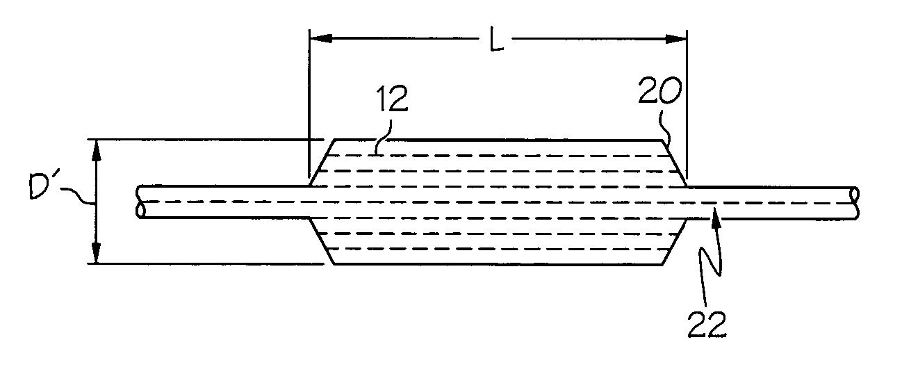
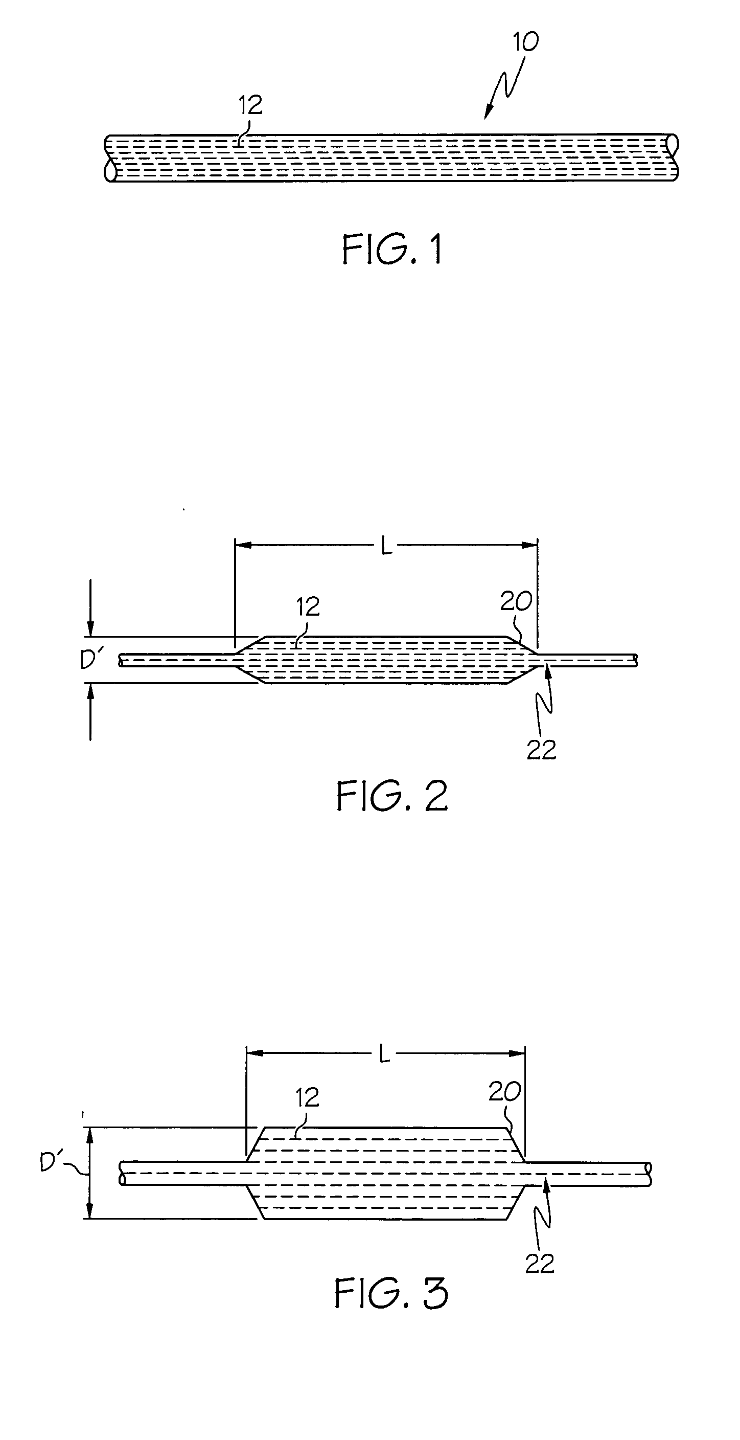
A known drawback of many previous delivery catheters and balloons is that when a balloon is radially inflated to a desired extent, the balloon will also expand longitudinally.
As a result of longitudinal expansion of a balloon during the delivery of a medical device, the balloon itself, the medical device mounted thereupon or both apparatuses may be shifted from their pre-inflation position resulting in improper delivery of the medical device.
In addition to potentially mis-delivering the medical device as described above, the resulting extended balloon may cause the edges of the stent to push against the vessel wall to a greater extent than they would from radial expansion alone.
The protruding stent edges may damage or tear the surrounding vessel resulting:in potentially serious trauma for the patient.
Method used
View moreImage
Smart ImageViewing Examples

Examples
example 1
[0035] a matrix component of Pebax 7033 was mixed with a fibril component of LCP VECTRA LKX 1107 at the ratio of 95% to 5% respectively by weight. The mixture was extruded at a rate of 110 feet / minute line speed into tubing of 0.039 (outer diameter)×0.027 (inner diameter) inch. A 3.5 mm balloon was formed from the resulting tubing by radial expansion at 110 degrees Celsius with blowing pressure of 350 psi. The balloon with double wall thickness of 0.0014 inch was inflated from 4 atm to 13 atm at 1 atm increment and no measurable balloon length change was observed.
Login to View More PUM
| Property | Measurement | Unit |
|---|---|---|
| elongation | aaaaa | aaaaa |
| elongation | aaaaa | aaaaa |
| diameter | aaaaa | aaaaa |
Abstract
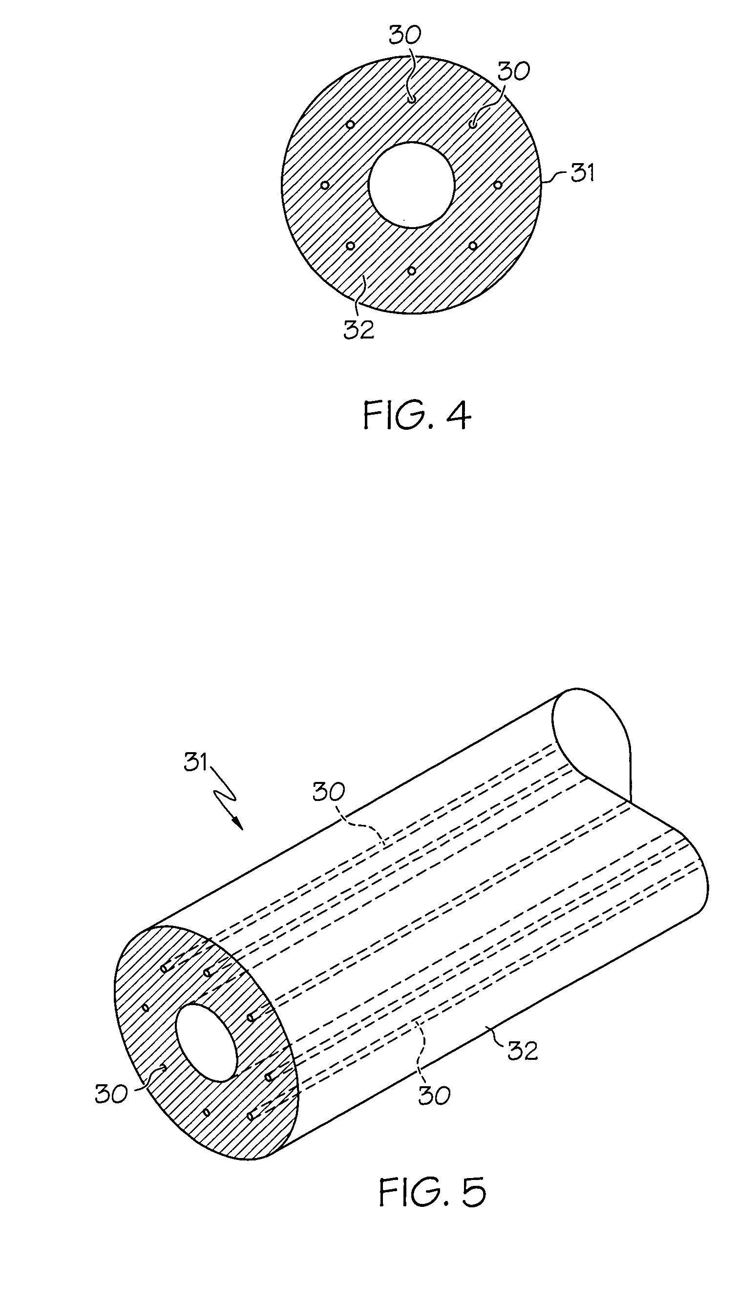
A medical balloon composed of a micro-composite material which provides for radial expansion of a balloon to a predetermined extent, but which has minimal longitudinal growth during balloon inflation. The micro-composite material includes a fibril component, a matrix component, and optionally, a compatibilizer. The fibril component may preferably be liquid crystal polymer fibers randomly scattered through out the balloon material. The liquid crystal polymers are created by extrusion at high speed. An alternative fibril component may be a PET fibers which are uniformly spaced about the balloon material and extend through out the length of the balloon material tube.
Description
CROSS-REFERENCE TO RELATED APPLICATIONS [0001] This application is a continuation-in-part of copending U.S. patent application Ser. No. 09 / 426384.BACKGROUND OF THE INVENTION [0002] Medical catheters having a balloon mounted thereon are useful in a variety of medical procedures. A balloon may be used to widen a vessel into which the catheter is inserted by dilating the blocked vessel, such as in an angioplasty procedure. More significant to the present invention however, is the use of a catheter to deliver a medical device, such as a stent, into a body lumen. Some examples of stent delivery balloons are disclosed in U.S. Pat. No. 5,702,418, and U.S. Pat. No. 5,797,877, the entire contents of both patents is hereby incorporated by reference. In these and other medical device delivery applications, radial expansion of a balloon may be used to expand or inflate a stent at a desired positioned within the body. Using a balloon equipped catheter to deliver a stent requires precise position...
Claims
Login to View More Application Information
Patent Timeline
 Patent Type & AuthorityApplications(United States)
IPC IPC(8): A61F2/06A61F2/84A61L29/04A61L29/14A61M25/00A61M25/10A61M29/00
CPCA61F2/958A61L29/049A61L29/14Y10T428/1352A61M25/1029A61M2025/1084B29L2031/7542A61M25/10
InventorCHEN, JOHN JIANHUAWANG, LIXIAOWANG, YIQUNCHIN, ALBERT C.C.
OwnerBOSTON SCI SCIMED INC