

Plug for use in left atrial appendage
a technology for atrial appendages and plugs, which is applied in the field of plugs for use in left atrial appendages, can solve the problems of highly biocompatible devices, and achieve the effects of reducing the risk of clot formation
- Summary
- Abstract
- Description
- Claims
- Application Information
AI Technical Summary
Benefits of technology
Problems solved by technology
Method used
Image

Examples
Embodiment Construction
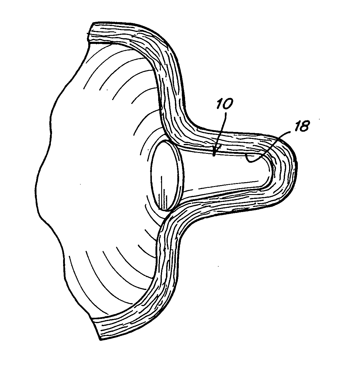
[0017] Embodiments of the device include a single piece plug of material that is inserted into the left atrial appendage (LAA) cavity to occlude it and seal it off from the blood flow that passes through the left atrial chamber. The profile of the plug is similar to that of the LAA itself so that the device will seat in the LAA and conform to the anatomy of the LAA. Its cross section could be axisymmetric or non-uniform.
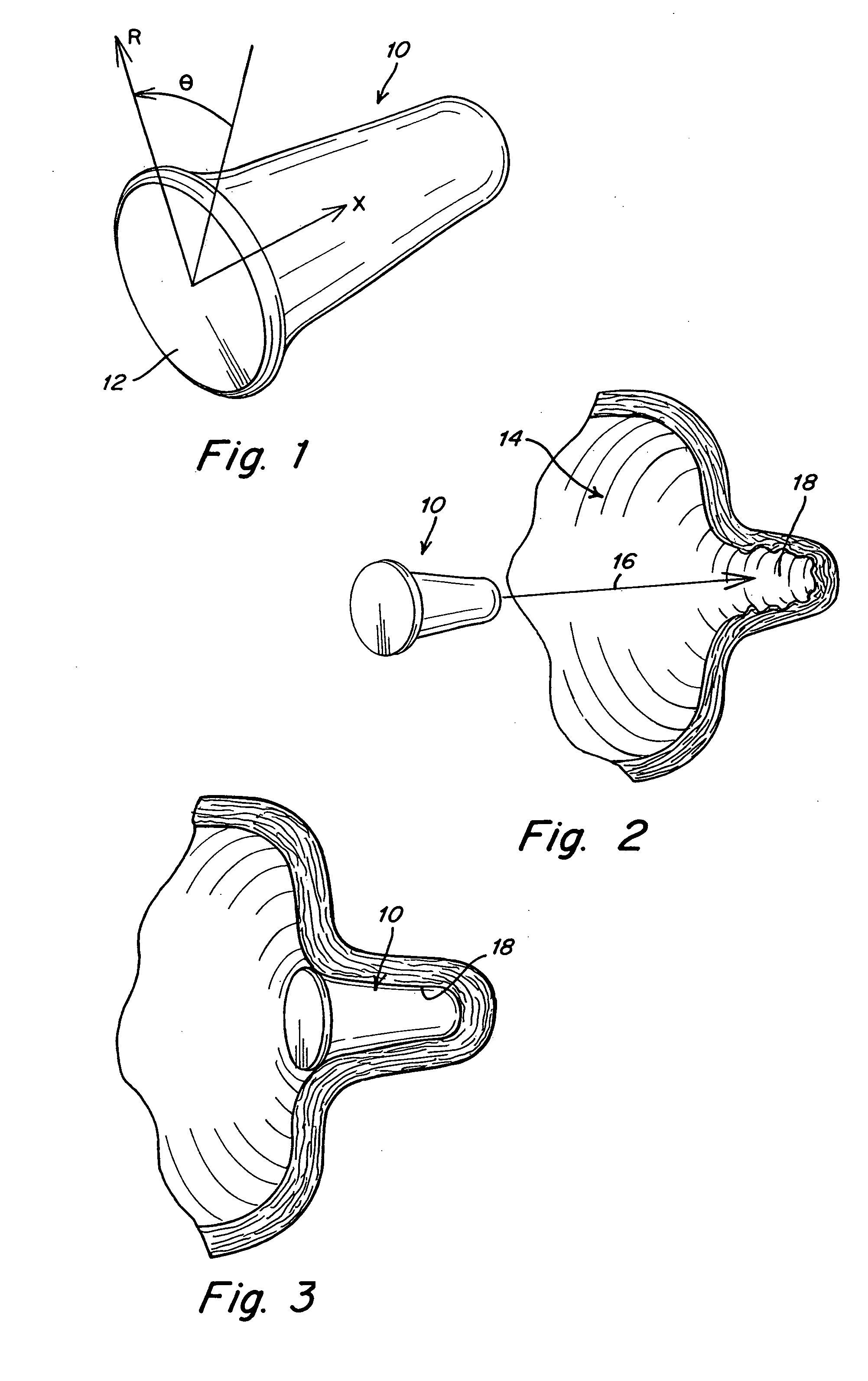
[0018] Referring to FIG. 1, a plug 10 for occluding the LAA has a flat proximal surface 12 that comes into contact with blood that flows through the left atrial chamber. The design depicted is axisymmetric and the principle cylindrical coordinate axes are labeled in the radial (R), longitudinal (X), and circumferential (θ) directions. The plug is inserted into the LAA cavity, which in the case of a completely solid plug, can completely fill the volume of the LAA cavity thereby occluding the appendage, or it can at least fill an inner portion of the LAA, such as abou...
PUM
 Abstract
Description
Claims
Application Information