Grid dividing method, grid dividing apparatus, computer readable recording medium recorded thereon grid dividing program, and computer readable recording medium recorded thereon data converting program

a grid dividing and computer technology, applied in cad techniques, instruments, design optimisation/simulation, etc., can solve the problems of long time required for grid division or numerical analysis, and inability to set grid division according to the situation in the present grid generating software, etc., to achieve high speed

Inactive Publication Date: 2005-10-20
FUJITSU LTD
View PDF9 Cites 8 Cited by
  • Summary
  • Abstract
  • Description
  • Claims
  • Application Information

AI Technical Summary

Benefits of technology

[0019] In cube division, a component whose result of analysis should be watched is first divided into cubes, whereby fundamental elements are finely generated in the watched component, whereas the fundamental elements are coarsely generated in components other than the above. On this occasion, each component is divided into cubes of the maximum size within an aspect ratio allowable range. Thus, it is possible to perform the cube division without increasing the number of fundamental elements (the number of grids).
[0020] In grid division, a result of cube division of a cube division model can be used as it is as a result of grid division. It is thereby possible to perform grid division (fundamental element generation) at very high speed with the use of existing grid generating software without changing the grid generating software.

Problems solved by technology

When the number of grids is large as this, the precision of analysis with the use of software for numerical analysis is improved, but a long time is required for grid division or numerical analysis.
Thus, it is impossible to set grid division according to the situation.
However, a setting according to the situation is impossible in the present grid generating software.

Method used


Image

  • Grid dividing method, grid dividing apparatus, computer readable recording medium recorded thereon grid dividing program, and computer readable recording medium recorded thereon data converting program
  • Grid dividing method, grid dividing apparatus, computer readable recording medium recorded thereon grid dividing program, and computer readable recording medium recorded thereon data converting program
  • Grid dividing method, grid dividing apparatus, computer readable recording medium recorded thereon grid dividing program, and computer readable recording medium recorded thereon data converting program

Examples


Embodiment Construction

[0034] Hereinafter, description will be made of an embodiment of the present invention with reference to the drawings.

(1) DESCRIPTION OF AN EMBODIMENT OF THE INVENTION

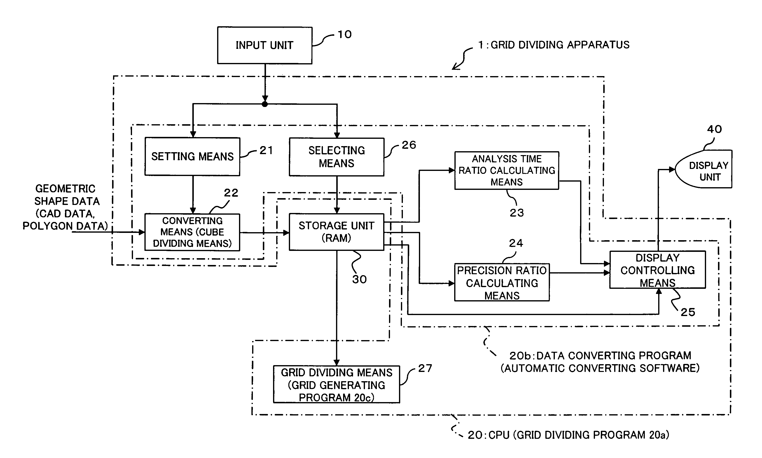
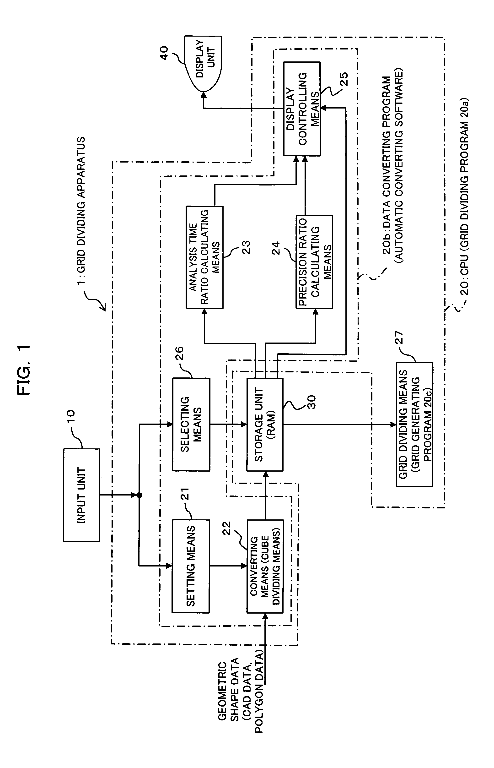
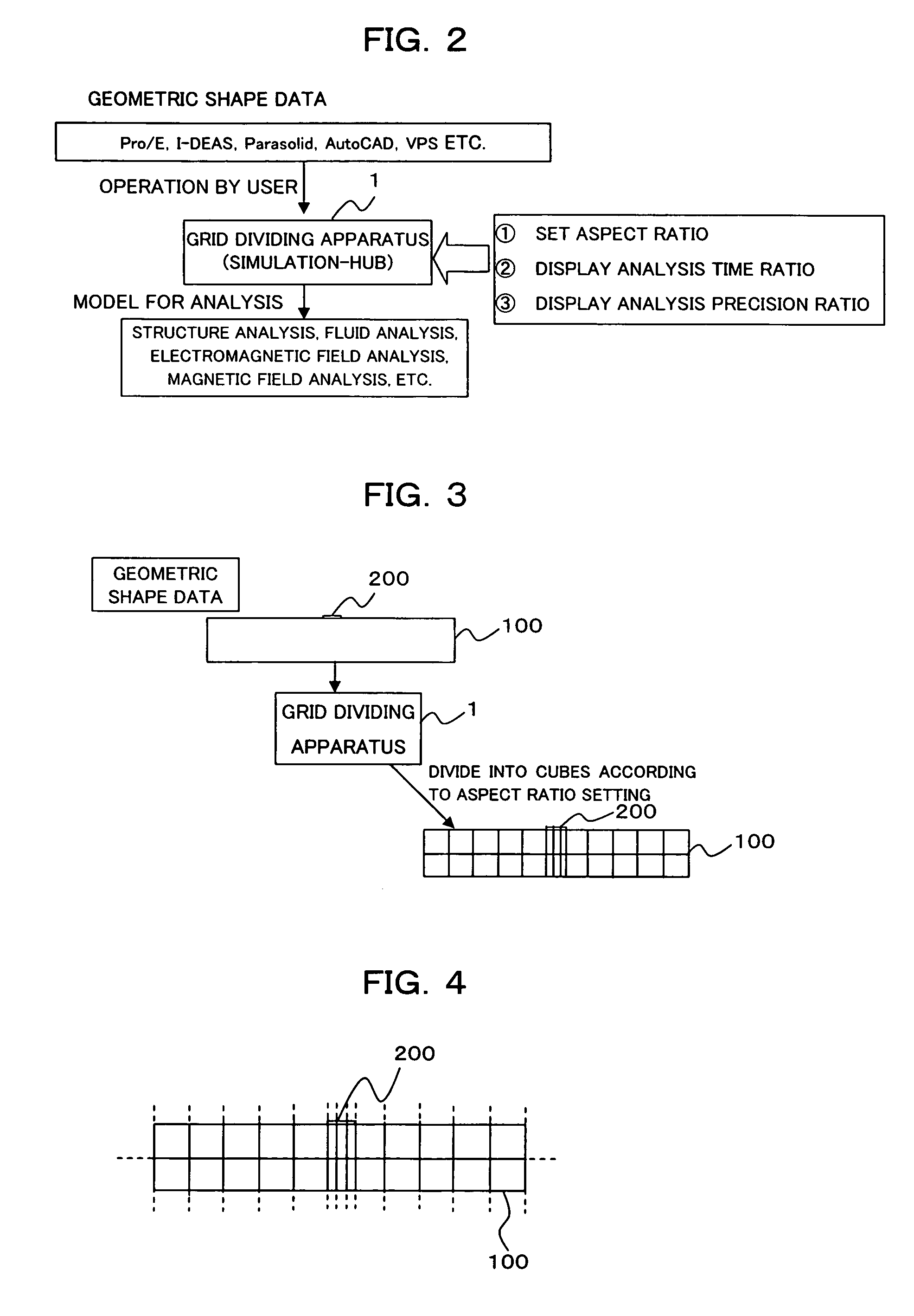
[0035]FIG. 1 is a block diagram showing a functional structure of a grid dividing apparatus according to an embodiment of this invention. A grid dividing apparatus 1 according to this embodiment shown in FIG. 1 is realized by executing a grid dividing program 20a including a data converting program 20b and a grid generating program 20c in an information processing apparatus such as a personal computer or the like. The grid dividing apparatus 1 comprises at least an input unit 10, a CPU 20, a storage unit 30 and a display unit 40.

[0036] The input unit 10 is operated by an operator or the like to instruct the CPU 20 to input aspect ratios or select a cube division model, as will be described later. The input unit 10 is comprised of a mouse, a keyboard or the like.

[0037] The CPU 20 executes the grid dividing program 2...


PUM


Abstract

In a technique for dividing an object, which is to be analyzed numerically and is made up of a plurality of components, into grids to generate fundamental elements, grid setting according to the situation becomes possible, and the time required for grid division or analysis can be shortened while securing sufficient precision of analysis. This invention involves a setting step of, in a data converting process, setting an allowable range of an aspect ratio of fundamental elements for numerical analysis to each of the components, a cube dividing step of, in the data converting process, dividing each of the components into a plurality of cubes within the aspect ratio allowable range to generate a cube division model, and a grid dividing step of dividing each of the components into grids according to the cube division model to generate fundamental elements for numerical analysis.

Description

TECHNICAL FIELD [0001] The present invention relates to a technique for dividing an object, which is to be analyzed numerically and is made up of a plurality of components, into grids to generate fundamental elements for numerical analysis. Particularly, the present invention relates to a technique for, when geometric shape data [for example, polygon data, CAD (Computer Aided Design) data] of the object to be analyzed numerically is converted into data for numerical analysis, dividing each of the components into cubes to divide the object to be analyzed numerically into grids. BACKGROUND ART [0002] When numerical analysis such as structure analysis, mechanism analysis, heat transfer analysis, fluid analysis, thermal fluid analysis, electromagnetic field analysis, magnetic field analysis or the like is performed with the use of a computer, it is general that an object to be analyzed numerically is divided into grids (mesh division) to generate cubic (solid, rectangular parallelepiped...

Claims


Application Information

Patent Timeline
Patent Type & Authority Applications(United States)
IPC IPC(8): G06F17/10G06F17/50G06T17/20
CPCG06F17/5018G06T17/20G06F2217/16G06F2111/10G06F30/23
Inventor SAKAIRI, MAKOTONAKADATE, MAMI
Owner FUJITSU LTD
Why Eureka
Try Eureka