

Storage system
- Summary
- Abstract
- Description
- Claims
- Application Information
AI Technical Summary
Benefits of technology
Problems solved by technology
Method used
Image

Examples
first embodiment
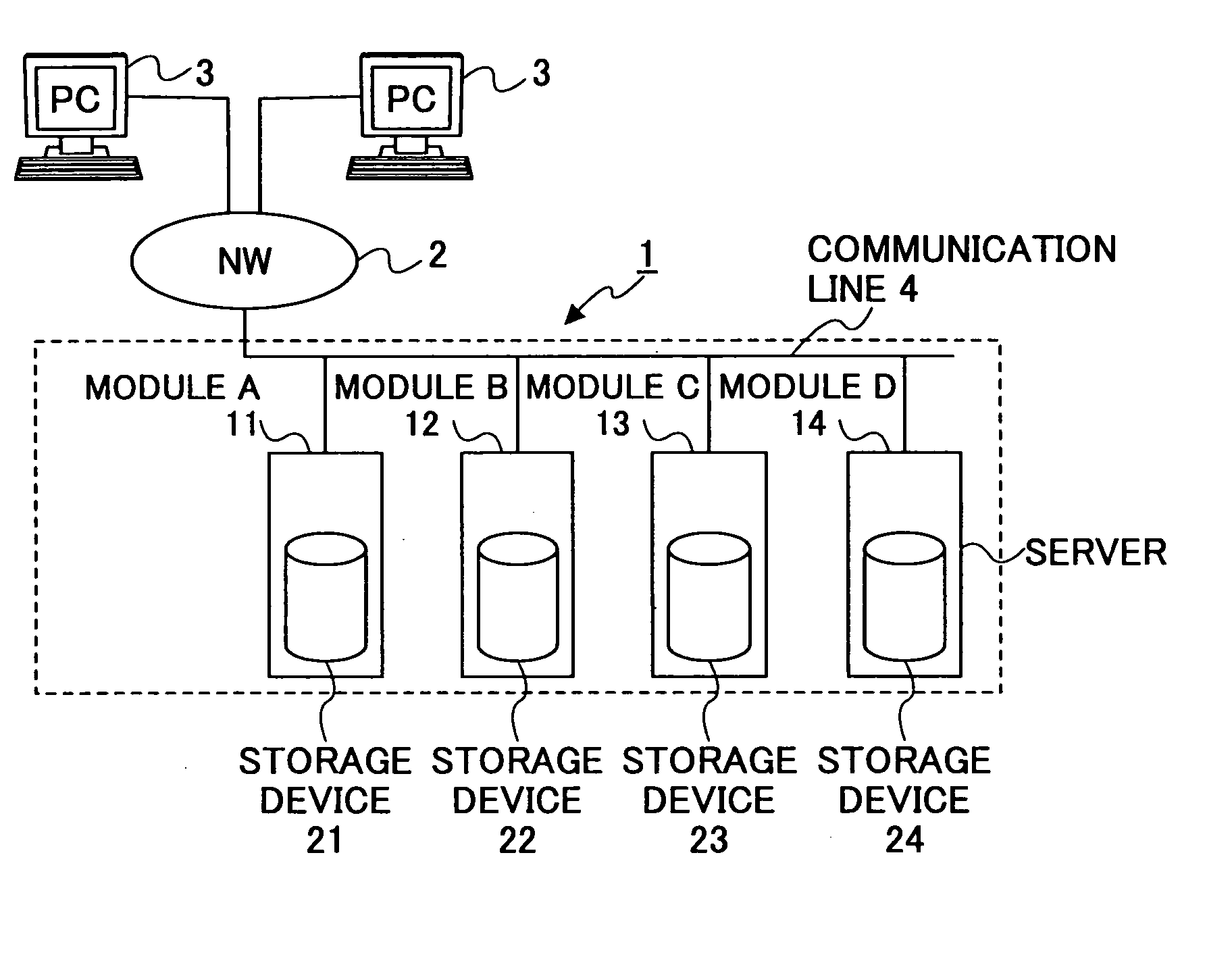
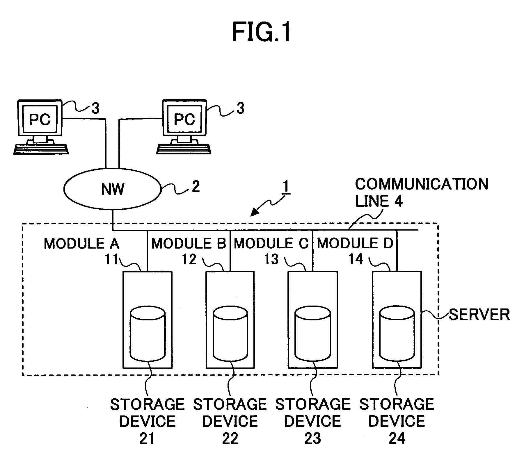
[0090]FIG. 1 is a schematic block diagram showing a configuration example of an information processing system including a storage system 1 of a first embodiment of the present invention.
[0091] As shown in FIG. 1, the storage system 1 is provided with a module A11 comprising a server (which may be a personal computer or a work station) having a storage device 21, a module B12 comprising a server having a storage device 22, a module C13 comprising a server having a storage device 23, and a module D14 comprising a server having a storage device 24. These four modules A11 through D14 are connected to a network 2 via communication lines 4. Two computers 3 are connected to the network 2. Each of the computers 3 can make requests for data storage, addition, deletion and change by accessing the storage system 1. The storage devices 21 through 24 are hard disks in this embodiment, although not they are limited to being hard disks.
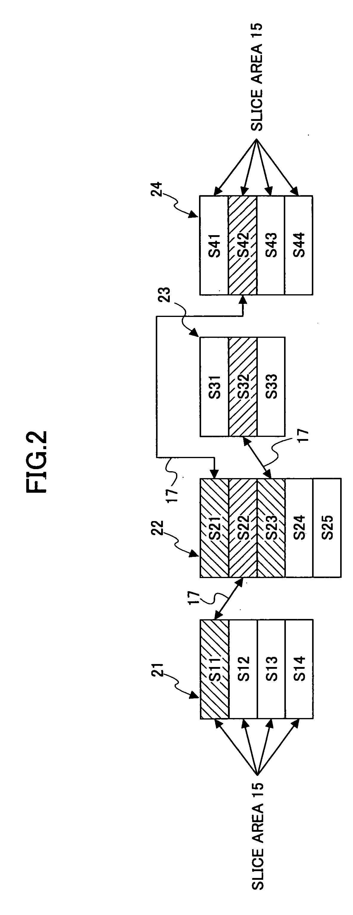
[0092] The four modules A11 through D14 provided in the stor...
second embodiment
[0160] A storage system of a second embodiment is the same as the storage system of the first embodiment except that access modules (which are described in detail below) are provided to directly access a corresponding slice area upon reception of a request for access to the storage system.
[0161]FIG. 28 is a schematic block diagram showing a configuration example of an information processing system including the storage system 1 of the second embodiment.
[0162] As shown in FIG. 28, the storage system 1 is provided with a module A11 comprising a server (which may be a personal computer or a work station) having a storage device 21, a module B12 comprising a server having a storage device 22, a module C13 comprising a server having a storage device 23, a module D14 comprising a server having a storage device 24, and two access modules A41 and B42 each comprising a personal computer (referred to as “PC” hereinafter) having information for allowing direct access to a slice area in a cor...
third embodiment
[0170] A third embodiment of the present invention is the same as the first embodiment except that a storage system comprises a state-control module for controlling the state of each module and a volume-information module for reconstructing information of each logical volume of which data elements are stored across the modules, and that the storage system is operated under the initiative of the volume-information module. Therefore, the following description focuses on these differences.
[0171]FIG. 30 is a schematic block diagram showing a configuration example of an information processing system including a storage system 1 of the third embodiment.
[0172] Referring to FIG. 30, the storage system 1 is provided with four modules G31, H32, I33 and J34 each comprising a PC having a storage device. The four modules G31 through J34 are connected to a network 2 via communication lines 4. The storage system 1 is further provided with two management-control modules 61 and 62 each comprising ...
PUM
 Abstract
Description
Claims
Application Information