Illuminant device

a technology of illumination device and light source, which is applied in the direction of lighting and heating apparatus, semiconductor devices for light sources, and light support devices with high power, can solve the problems of reducing light output, accelerating aging, and prone to heat dissipation of leds with higher power, so as to increase light use efficiency and extend the service time of lighting modules

Inactive Publication Date: 2015-01-08
LEDIAMOND OPTO
View PDF9 Cites 2 Cited by
  • Summary
  • Abstract
  • Description
  • Claims
  • Application Information

AI Technical Summary

Benefits of technology

[0007]It is an object to provide an illuminant device having transparent heat-dissipating component to conduct heat generated from operating illuminant device, and having advantaged of high usage efficiency.
[0009]In an embodiment of the present invention, a thermal conductivity of the first transparent heat-dissipating component is higher than 0.2 W / mK. Moreover, the first transparent heat-dissipating component comprises a first plane. The area of the first plane is larger than that of the first surface, so that the first transparent heat-dissipating component can effectively conduct heat generated by the lighting module. The second transparent heat-dissipating component comprises a second plane. The area of the second plane is larger than that of the second surface, so that the second transparent heat-dissipating component can effectively conduct heat generated by the lighting module. In an embodiment of the present invention, the illuminant device further comprises a second transparent heat-dissipating component arranged on the second transparent resin layer and opposite to the transparent substrate.
[0012]In an embodiment of the present invention, the heat-dissipating blocks are arranged with an interval, so that heat can be rapidly conducted from the illuminant device.
[0018]The first transparent heat-dissipating component can effectively conduct heat generated by the lighting module, so that service time of the lighting module can be extended, and phenomena of luminous decay and color shifting can be prevented to increase light use efficiency.

Problems solved by technology

However, in comparison to other lighting source, LEDs with higher power are more prone to a problem of heat dissipation.
In general, over-temperature operation makes the LEDs to have reduced light output (light decay) and color shift and accelerates aging to shorten the lifetime of the LEDs.
However, the opaque heat-dissipating component inevitably shields light emitted from the LEDs to reduce light usage efficiency of the LED light module.

Method used


Image

  • Illuminant device
  • Illuminant device
  • Illuminant device

Examples


first embodiment

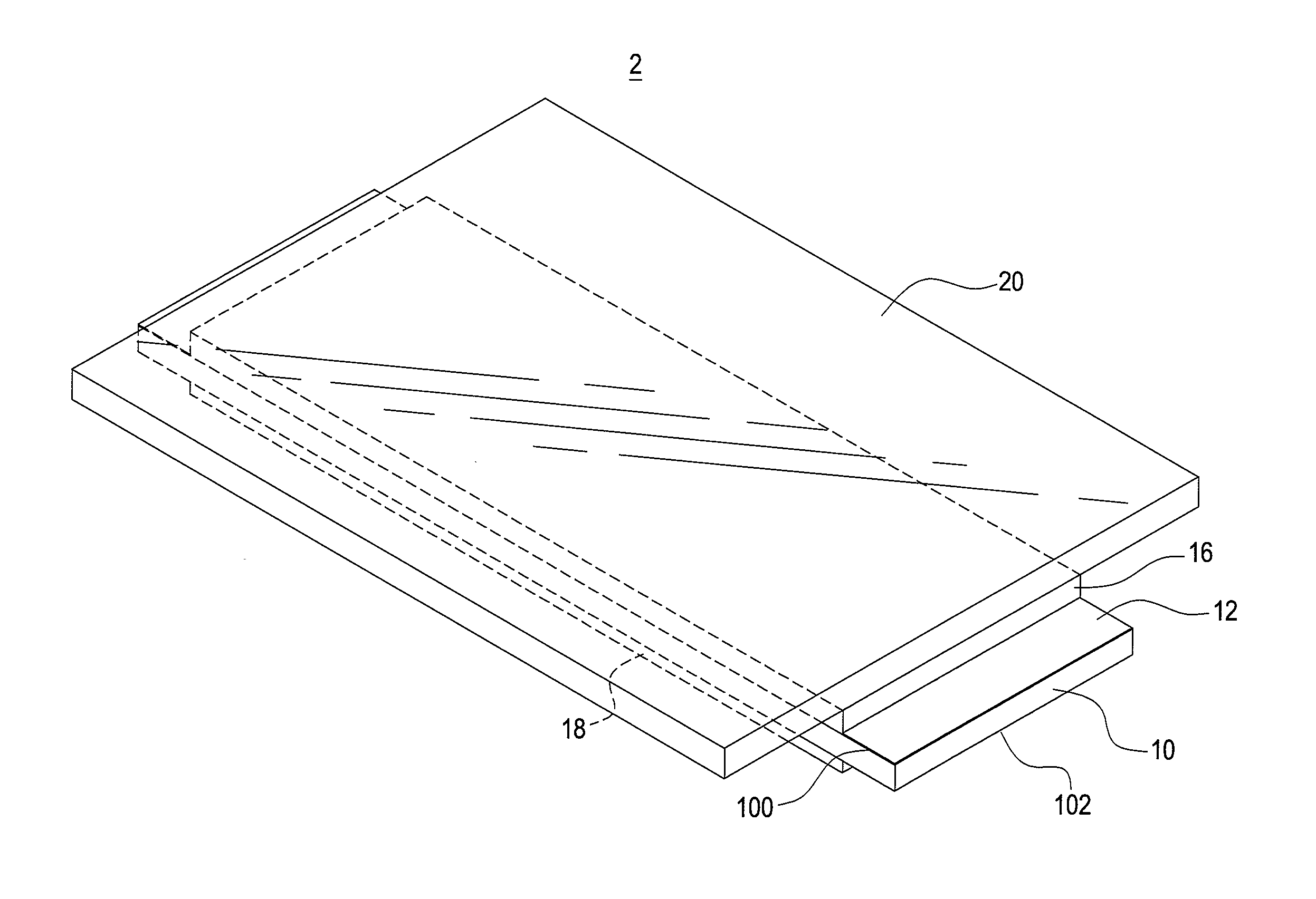
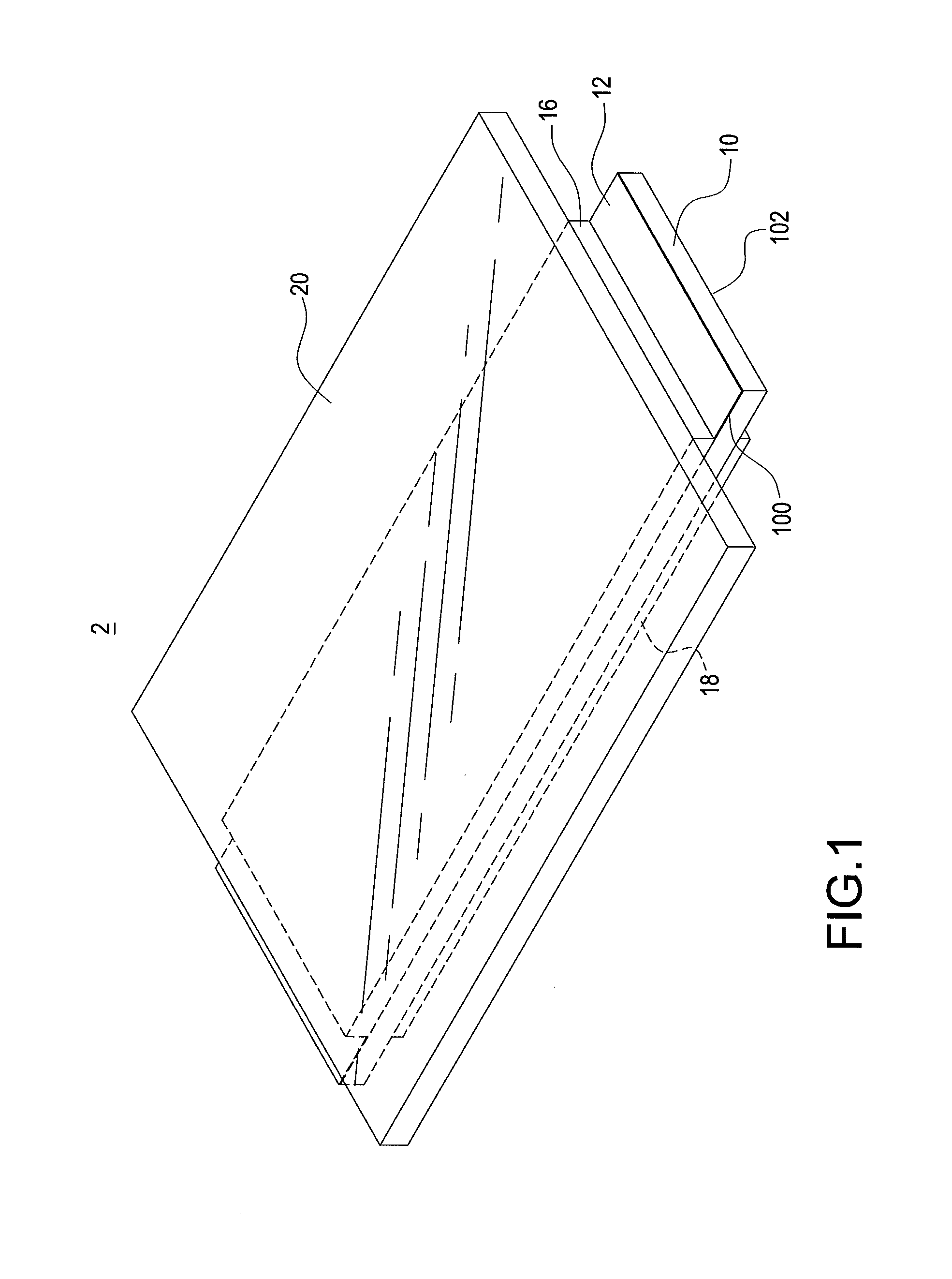
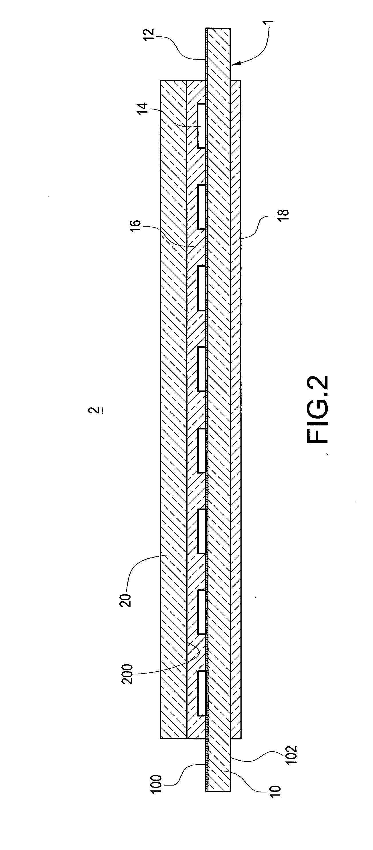
[0031]Reference is made to FIG. 1 and FIG. 2, which are respectively a perspective view and a sectional view of an illuminant device according to the present invention. The illuminant device 2 includes a lighting module 1 (as shown in FIG. 3 and FIG. 4) and a first transparent heat-dissipating component 20. The lighting module 1 includes a transparent substrate 10, a circuit layer 12, a plurality of light emitting diode (LED) dies 14, a first transparent resin layer 16, and a second transparent resin layer 18. The transparent substrate 10 includes a first surface 100 and a second surface 102 opposite to the first surface 100. The transparent substrate 10 is, for example, made of quartz or glass allowing light emitted from the LED dies 14 transmitting therethrough. In this embodiment, a profile of the transparent substrate 10 is rectangular, and the first surface 100 and the second surface 102 are two planes having larger area on two opposite faces of the transparent substrate 10.

[00...

third embodiment

[0042]Reference is made to FIG. 8 and FIG. 9, which are respectively a perspective view and a sectional view of an illuminant device according to a forth embodiment of the present invention. The illuminant device 2C is similar to the illuminant device 2B mentioned in the third embodiment, and the same reference numbers are used in the drawings and the description to refer to the same parts. It should be noted that the illuminant device 2C further includes a first phosphor layer 24 and a second phosphor layer 26.

[0043]The first phosphor layer 24 is disposed on the first transparent heat-dissipating component 20 and opposite to the first transparent resin layer 16. The first phosphor layer 24 is mixed with transparent resin and phosphor, and is excited by partial light emitted from the LED dies 14 and then converts the light into a first wavelength-converted light, which is to be mixed with the other light emitted from the LED dies 14 to generate a light with demand color. In this emb...


PUM


Abstract

An illuminant device includes a lighting module and a first transparent heat-dissipating component. The lighting module includes a transparent substrate, a circuit layer, a plurality of light emitting diode (LED) dies, a first transparent resin layer, and a second transparent resin layer. The transparent substrate includes a first surface and a second surface opposite to the first surface. The circuit layer is placed on the first surface. The LED dies are placed on the first surface and electrically connected to the circuit layer. The first transparent resin layer is disposed on the first surface and covers the light emitting diode dies. The second transparent resin layer is disposed on the second surface and corresponding to the first transparent resin layer. The first transparent heat-dissipating component is arranged on the first transparent resin layer and opposite to the transparent substrate.

Description

BACKGROUND OF THE INVENTION[0001]1. Field of the Invention[0002]The present invention relates to an illuminant device, and in particular to an light emitting diode (LED) illuminant device with transparent heat-dissipating component.[0003]2. Description of Related Art[0004]A light emitting diode (LED) is a kind of semiconductor device, which exploits the property of direct-bandgap semiconductor material to convert electric energy into light energy efficiently and has the advantages of long service time, high stability and low power consumption and is developed to replace the traditional non-directivity light tube and incandescent lamp.[0005]However, in comparison to other lighting source, LEDs with higher power are more prone to a problem of heat dissipation. The main reason is that the heat of the LEDs cannot be dissipated through infrared radiation. In general, over-temperature operation makes the LEDs to have reduced light output (light decay) and color shift and accelerates aging...

Claims


Application Information

Patent Timeline
Patent Type & Authority Applications(United States)
IPC IPC(8): F21V29/00F21K99/00
CPCF21V29/22F21K9/56F21K9/30H01L25/0753H01L33/641H01L2924/0002H01L2924/00
Inventor CHEN, PENG-YUTSENG, CHUNG-TING
Owner LEDIAMOND OPTO
Why Eureka
Try Eureka