Polishing method and polishing pad
- Summary
- Abstract
- Description
- Claims
- Application Information
AI Technical Summary
Benefits of technology
Problems solved by technology
Method used
Image
Examples
first embodiment
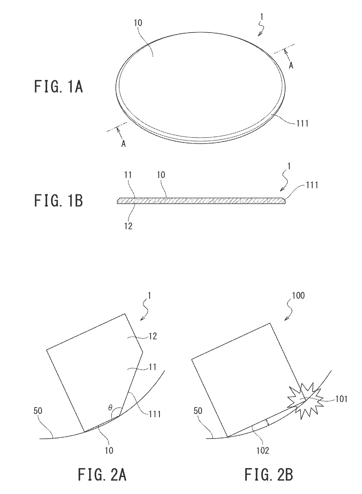
[0045]The following describes a method of the first embodiment with reference to FIGS. 1A to 2B.
[0046]The polishing method of this embodiment uses a disc-shaped polishing pad 1 illustrated in FIGS. 1A and B.
[0047]The polishing pad 1 is a suede type or a nonwoven fabric type polishing pad and has a thickness of 0.5 mm or more and 5.0 mm or less. The hardness of the polishing pad 1 is C hardness of 40 or more and 90 or less.
[0048]The polishing pad 1 is divided into a part (an end portion) 11 on a polishing surface 10 side and a part (a base portion) 12 on a side opposite to the polishing surface 10 in an axial direction of the disc. A peripheral surface 111 of the end portion 11 is a tapered surface whose diameter is reduced to the polishing surface 10. An angle θ (see FIG. 2A) formed by the peripheral surface 111 and the polishing surface 10 is 125° or more and less than 180°. That is, a corner portion of the end portion 11 is chamfered into an inclined surface shape.
[0049]A method t...
second embodiment
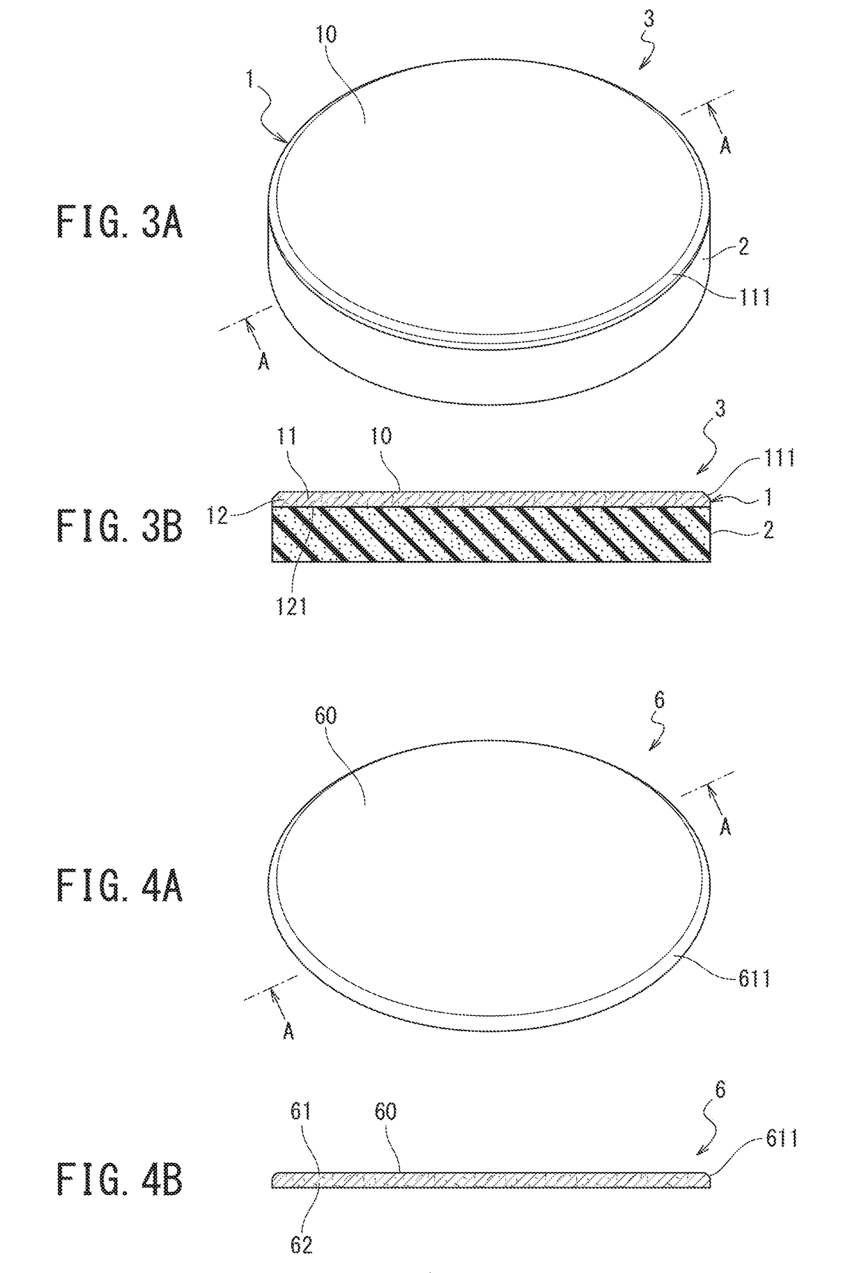
[0055]A polishing method of this embodiment uses a polishing pad with support layer 3 illustrated in FIGS. 3A and 3B.
[0056]The polishing pad with support layer 3 is constituted of the polishing pad 1 of the first embodiment and a support layer 2 made of foamed polyurethane softer than the polishing pad 1. The support layer 2 is fixed to a surface 121 on a side opposite to the polishing surface 10 of the polishing pad 1 with adhesive or a double-sided tape. The support layer 2 has a thickness of 2.0 mm or more and 50 mm or less.
[0057]The polishing method of this embodiment ensures obtaining effects identical to those of the polishing method of the first embodiment by the function of the polishing pad 1. Additionally, since the polishing pad with support layer 3 of a two-layer structure where the soft support layer 2 is fixed is used, the following effect can also be obtained.
[0058]When force given from a polishing device to the soft support layer 2 is transmitted to the polishing pad...
third embodiment
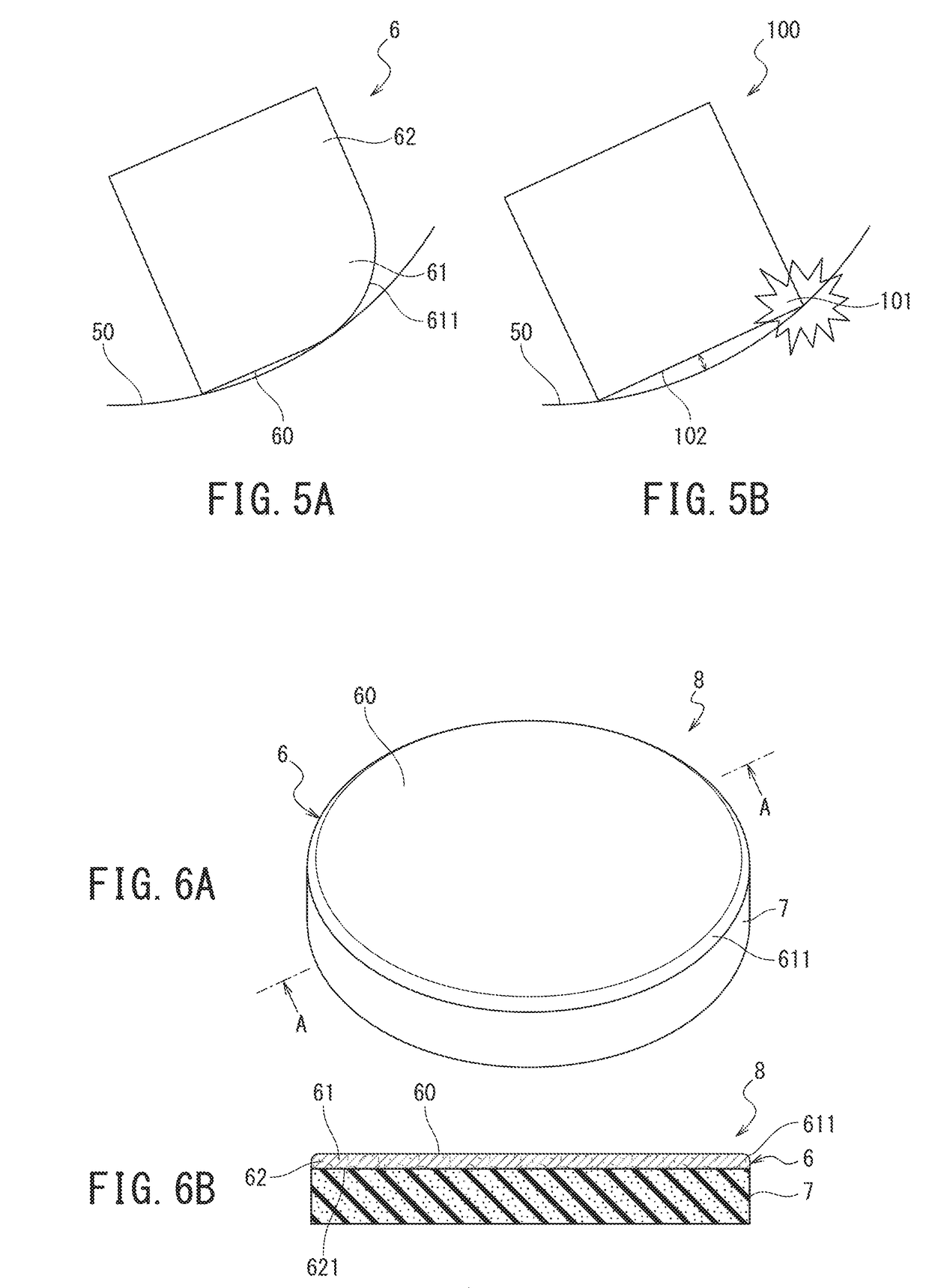
[0059]The following describes a method of the third embodiment with reference to FIGS. 4A to 5B.
[0060]The polishing method of this embodiment uses a disc-shaped polishing pad 6 illustrated in FIGS. 4A and 4B.
[0061]The polishing pad 6 is a suede type or a nonwoven fabric type polishing pad and has a thickness of 0.5 mm or more and 5.0 mm or less. The hardness of the polishing pad 6 is C hardness of 40 or more and 90 or less.
[0062]The polishing pad 6 is divided into a part (an end portion) 61 on a polishing surface 60 side and a part (a base portion) 62 on a side opposite to the polishing surface 60 in an axial direction of the disc. A peripheral surface 611 of the end portion 61 is an arc surface. That is, a corner portion of the end portion 61 is roundly chamfered.
[0063]A method to roundly chamfer the corner portion includes a cutting method. An example of the cutting includes a method that moves a sander or a circular cutting edge, which rotates at high speed, while pressing the sa...
PUM
 Abstract
Description
Claims
Application Information
 - R&D
- Intellectual Property
- Life Sciences
- Materials
- Tech Scout
- Unparalleled Data Quality
- Higher Quality Content
- 60% Fewer Hallucinations
Browse by: Latest US Patents, China's latest patents, Technical Efficacy Thesaurus, Application Domain, Technology Topic, Popular Technical Reports.
© 2025 PatSnap. All rights reserved.Legal|Privacy policy|Modern Slavery Act Transparency Statement|Sitemap|About US| Contact US: help@patsnap.com


