Solar control film and manufacturing method thereof

a technology of solar control film and manufacturing method, applied in the direction of door/window protective device, semiconductor/solid-state device details, coatings, etc., can solve the problems of poor indoor illumination from daylight, easy to understand, and sourcing of in usually forms a problem, so as to reduce reduce production costs, and achieve the effect of reducing the replacement frequency of targets

Inactive Publication Date: 2019-05-02
INST NUCLEAR ENERGY RES ROCAEC
View PDF0 Cites 0 Cited by
  • Summary
  • Abstract
  • Description
  • Claims
  • Application Information

AI Technical Summary

Benefits of technology

[0006]Accordingly, it is an object of the present invention to provide a solar control film and a method for manufacturing the solar control film, that can implement the targets more efficiently, reduce the replacement frequency of the targets, lower the production cost, simplify the production complexity, and improve the production efficiency. The solar control film produced in accordance with the present invention can be applied to windows of constructions and vehicles.

Problems solved by technology

It is easy to understand that indoor illumination from daylights would become poor while the sunshine is shaded for any kind of purposes or tools.
However, since the sputtering process used for forming the dielectric layer needs a special material indium (In), and the In is one of staple goods generally protected by its source country, thus the sourcing of the In usually forms a problem.
In addition, while in applying the sputtering process, a poisoning effect usually occurs at a target of a metal oxide.
Thus, monitoring this poisoning effect becomes important during the sputtering process, and thus the entire manufacturing difficulty would be raised.
In addition, by comparing to the conventional solar control film that includes a metal-oxide coating film produced by sputtering, since a poisoning effect usually occurs at a target of a metal oxide during the sputtering process, thus in-process monitoring of this poisoning effect becomes important, and thereby the entire manufacturing difficulty would be raised.

Method used


Image

  • Solar control film and manufacturing method thereof
  • Solar control film and manufacturing method thereof
  • Solar control film and manufacturing method thereof

Examples


first embodiment

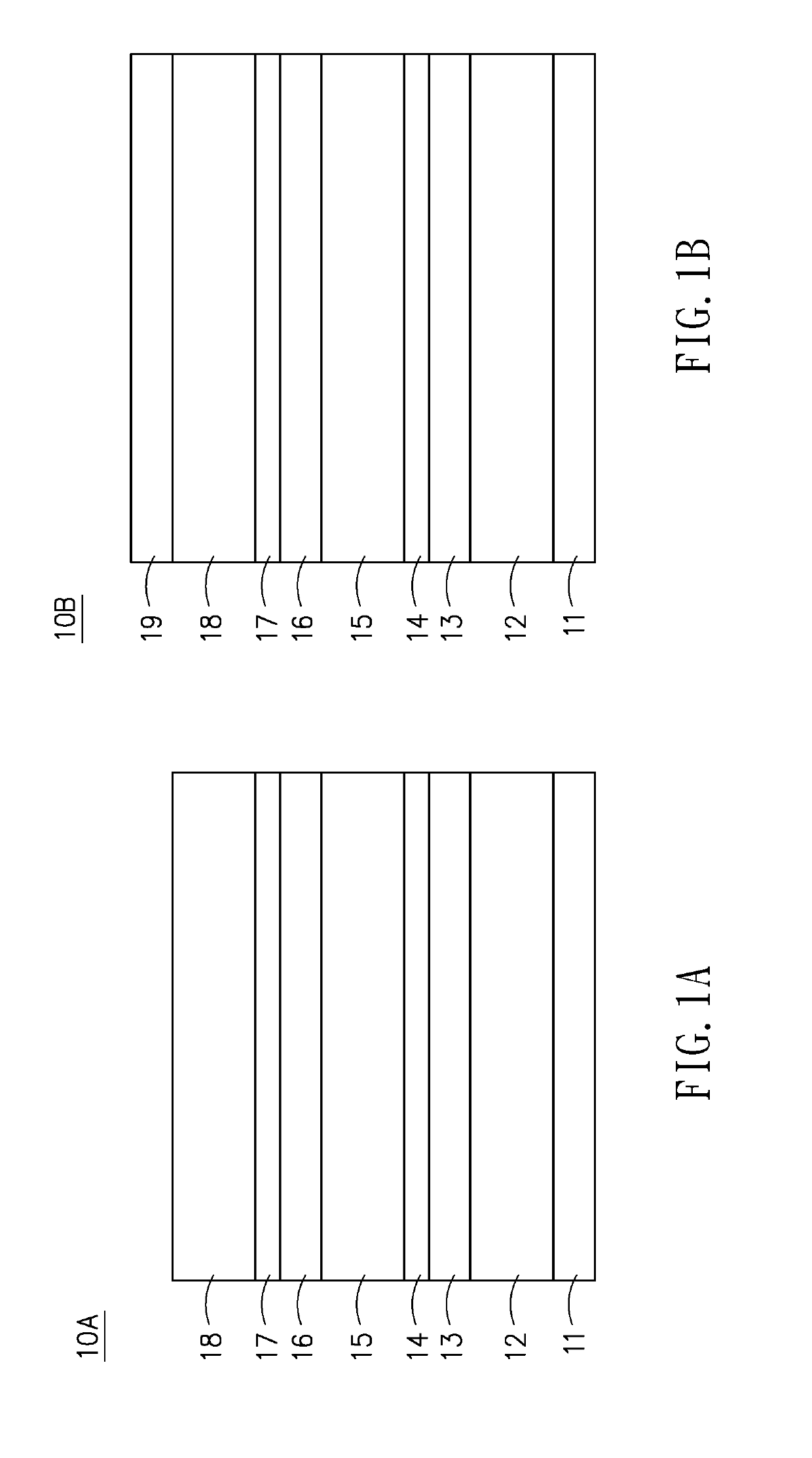
[0057]FIG. 4 is a flowchart of the method for manufacturing a solar control film in accordance with the present invention. In this embodiment, the method for manufacturing a solar control film S10, particularly for forming the solar control film 10B of FIG. 1B, includes the following Step S110 through Step S160.

[0058]In Step S110, an arc-plasma coating process is applied to deposit a first dielectric layer 12 on a soft substrate 11, in which a material of the first dielectric layer 12 contains Ti. In details, firstly, the soft substrate 11 made of a polyethylene terephthalate (PET) is provided. The soft substrate 11 is displaced into a chamber of an arc-plasma coating apparatus, and then the chamber is vacuumed. As the chamber is vacuumed to a predetermined degree, an oxygen is introduced into the chamber. Then, the arc-plasma coating process is performed to deposit the first dielectric layer 12 onto the soft substrate 11, so that the first dielectric layer 12 as a thin metal-oxide ...

second embodiment

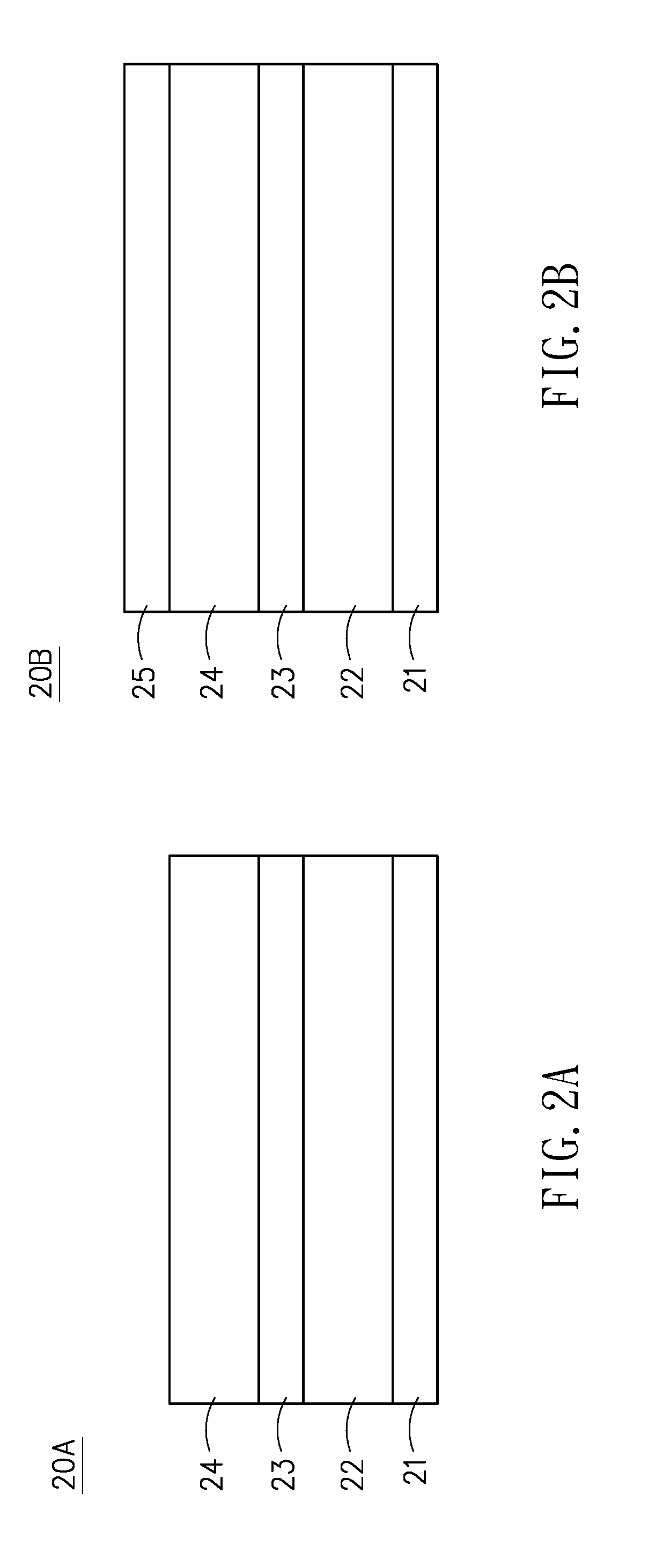
[0067]FIG. 5 is a flowchart of the method for manufacturing a solar control film in accordance with the present invention. As shown, in this embodiment, the method for manufacturing a solar control film S20, particularly for forming the solar control film 20B of FIG. 2B, includes the following Step S210 through Step S240.

[0068]In Step S210, an arc-plasma coating process is applied to deposit a first dielectric layer 22 on a soft substrate 21, in which a material of the first dielectric layer 22 contains Ti. In details, firstly, the soft substrate 21 made of a polyethylene terephthalate (PET) is provided. The soft substrate 21 is displaced into a chamber of an arc-plasma coating apparatus, and then the chamber is vacuumed. As the chamber is vacuumed to a predetermined degree, an oxygen is introduced into the chamber. Then, the arc-plasma coating process is performed to deposit the first dielectric layer 22 onto the soft substrate 21, so that the first dielectric layer 22 as a thin me...

third embodiment

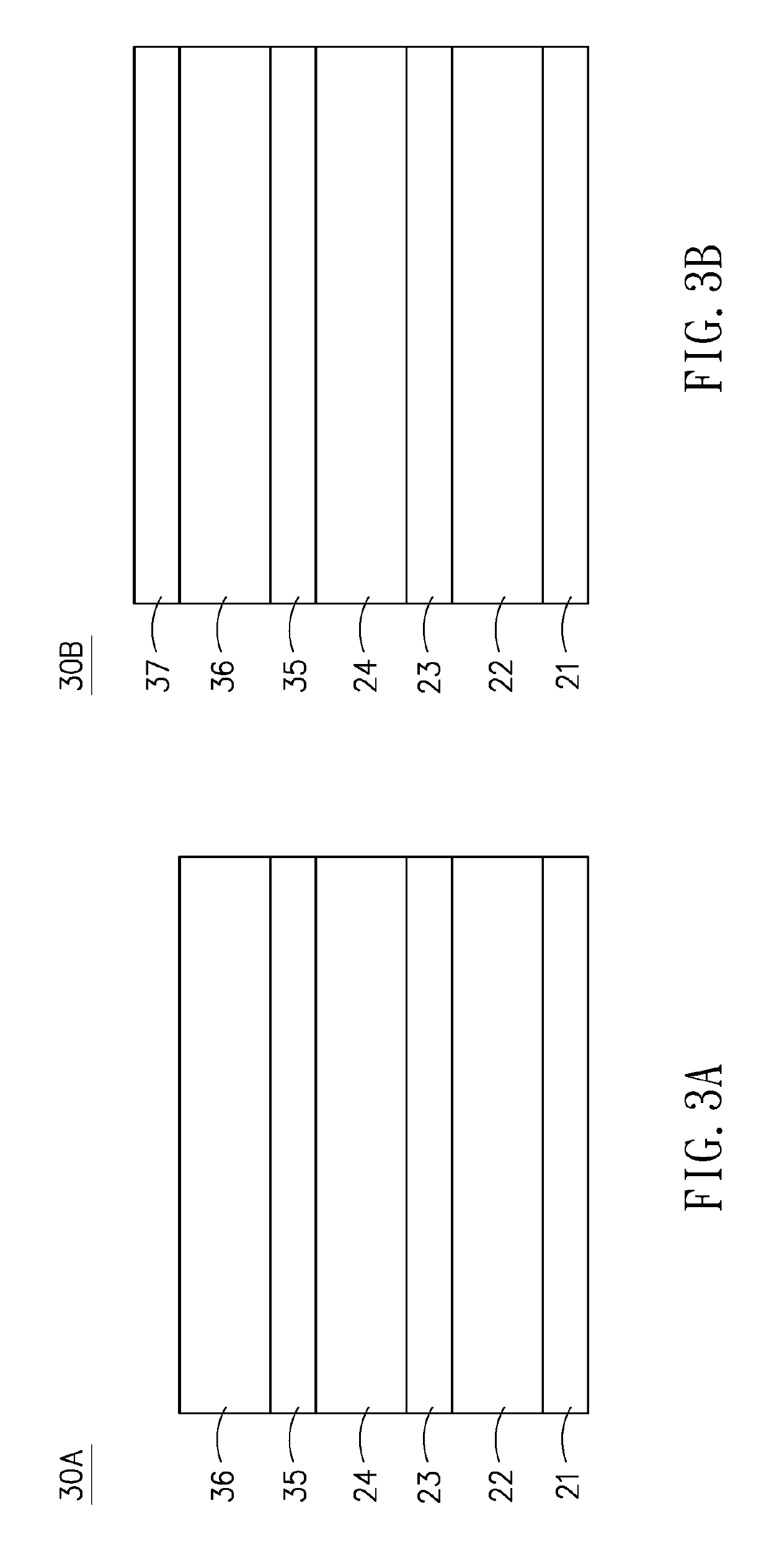
[0075]FIG. 6 is a flowchart of the method for manufacturing a solar control film in accordance with the present invention. In this embodiment, the method for manufacturing a solar control film S30 is relevant to form the solar control film 30B of FIG. 3B. It shall be explained that the method for manufacturing a solar control film S30 of FIG. 6 is resembled to that S20 of FIG. 5. In these two embodiments, the same elements would be assigned by the same number so as to indicate the same function they serve, but details thereabout would be omitted herein. Namely, in the following descriptions, only the differences in between would be elucidated. The major difference between FIG. 6 and FIG. 5 is that, after Step S230 of the method for manufacturing a solar control film S30 of this embodiment is performed, Step S340 to Step S360 are further included. In Step S340, a second conductive layer 35 is deposited on the second dielectric layer 24. The second conductive layer 35 contains TiN, an...


PUM

PropertyMeasurementUnit
thicknessaaaaaaaaaa
thicknessaaaaaaaaaa
thicknessaaaaaaaaaa

Abstract

A method for manufacturing a solar control film includes: a step of applying an arc-plasma coating process to deposit a first dielectric layer on a soft substrate, the first dielectric layer containing Ti; a step of depositing a first metal layer on the first dielectric layer; a step of applying the arc-plasma coating process to deposit a second dielectric layer on the first metal layer, the second dielectric layer containing the Ti; a step of depositing a second metal layer on the second dielectric layer; and, a step of applying the arc-plasma coating process to deposit a third dielectric layer on the second metal layer, the third dielectric layer containing the Ti. In addition, a solar control film is also provided.

Description

CROSS REFERENCE TO RELATED APPLICATION[0001]This application claims the benefit of Taiwan Patent Application Serial No. 106136976, filed on Oct. 26, 2017, the subject matter of which is incorporated herein by reference.BACKGROUND OF THE INVENTION(1) Field of the Invention[0002]The invention relates to a solar control film and a method for manufacturing the solar control film, and more particularly to the solar control film and the method for manufacturing the solar control film that apply an arc-plasma coating process to form dielectric layers for the solar control film.(2) Description of the Prior Art[0003]For a purpose of shading sunshine or reducing load of indoor air-conditioner, proper sun-shading tools are usually applied to windows of constructions or transportation vehicles. These sun-shading tools include various shutters, curtains, thermal-insulated papers and the like sun or solar control films. Generally, to obtain successful sun shading, trade-off shall be made between ...

Claims


Application Information

Patent Timeline
Patent Type & Authority Applications(United States)
IPC IPC(8): H01L31/18H01L21/02C23C16/40H01L23/29C03C17/23C03C17/34
CPCH01L31/18H01L21/02521C23C16/40H01L23/291C03C17/23C03C17/3417E06B9/24E06B2009/2464C03C17/36C03C17/361C03C17/3639C03C17/3644C03C17/3652C03C17/366C03C17/3681C03C17/3435C23C14/325C23C14/083
Inventor CHEN, EN-SHIHWU, TZONG-DAWHSIEH, CHENG-CHANGTSENG, CHING-PEILIU, YUNG-CHING
Owner INST NUCLEAR ENERGY RES ROCAEC
Why Eureka
Try Eureka