

Removing method of tube
a technology of tube and tube body, which is applied in the direction of discharge tube luminescnet screen, lighting and heating apparatus, electric/magnetic/electromagnetic heating, etc., can solve the problems of high cost of repairing damage, complicated operation, damage to /b>, etc., and achieves the effect of easy pulling out and removing and short tim
- Summary
- Abstract
- Description
- Claims
- Application Information
AI Technical Summary
Benefits of technology
Problems solved by technology
Method used
Image

Examples
Embodiment Construction
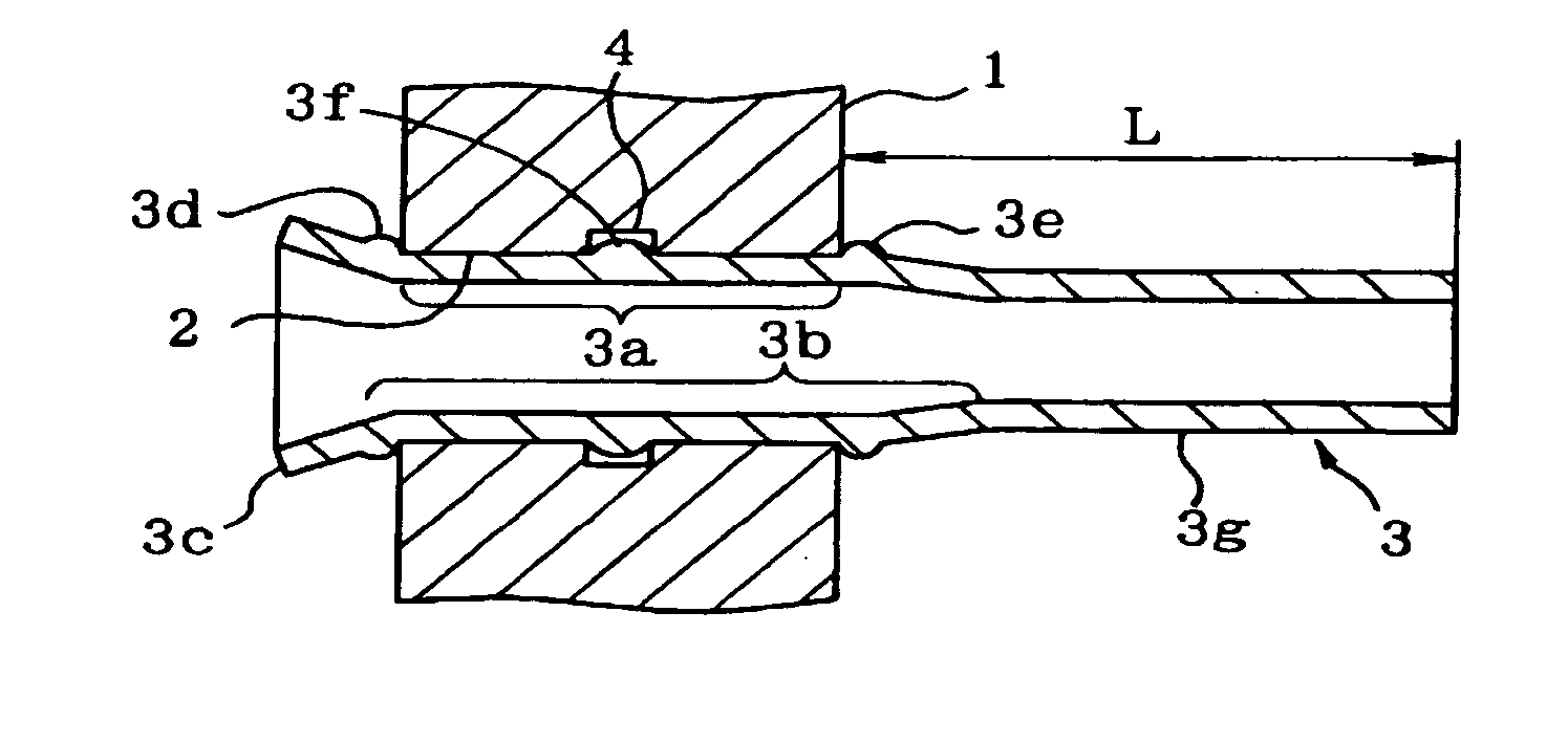
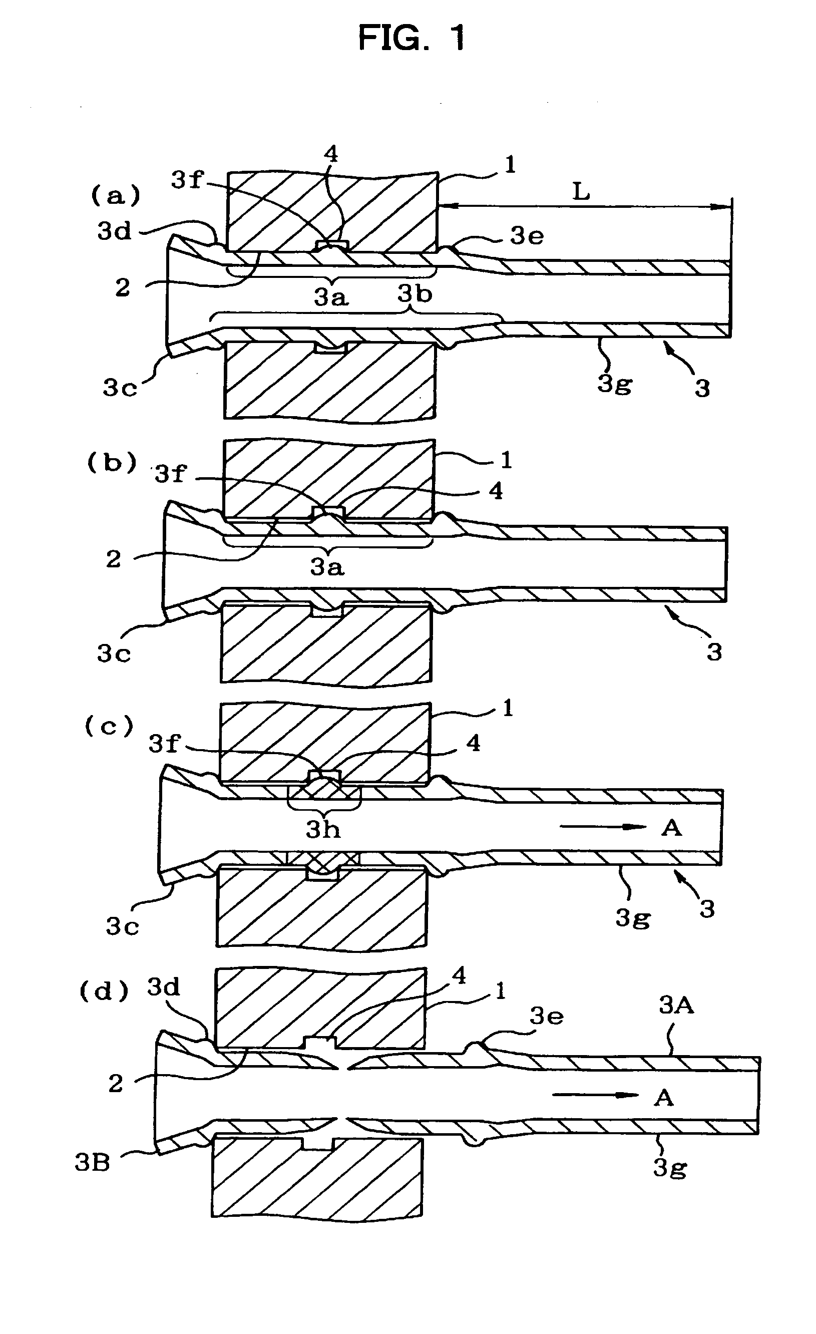
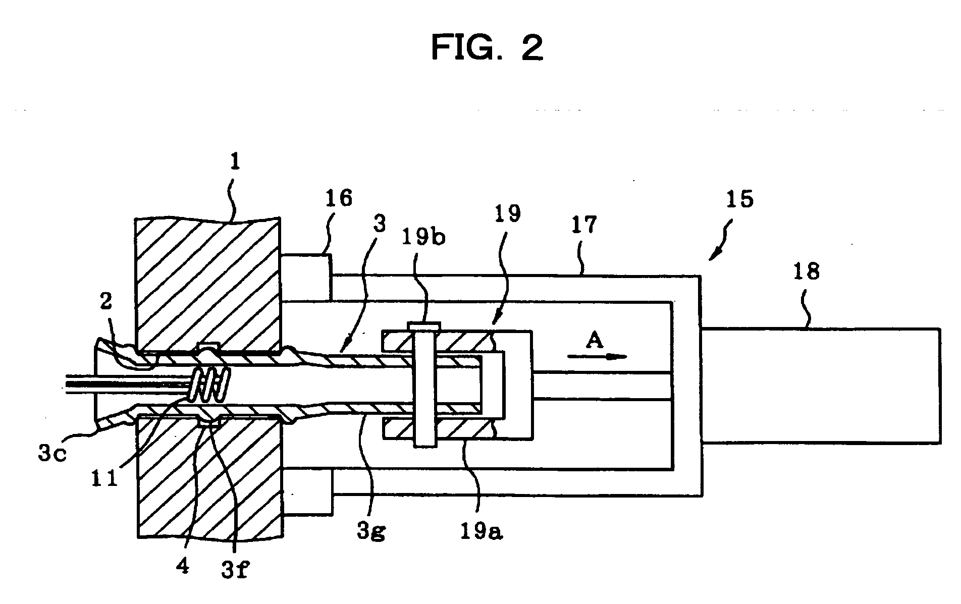
[0016] According to the present invention, after the diameter-increased region of the TUBE which is inserted into the tube-hole is reduced in diameter and is loosened, the region opposed to the groove of the tube-sheet is heated into the red-hot state and the TUBE is stretched in the axial direction, and the red-heated region is stretched to reduce the diameter and is cut off. With this configuration, when the region is heated into the red-hot state, heat transferring from the TUBE to the tube-sheet is small, and thus, the TUBE can effectively be heated, and when the red-heated region is stretched, the tractive force applied to the TUBE can effectively be applied to the red-heated region and with this, it is possible to stretch the red-heated region with a small tractive force to reduce its diameter, and thus, the diameter-increased portion formed on the region opposed to the groove can be reduced in diameter and the diameter-increased portion can be pulled out without being caught ...
PUM
| Property | Measurement | Unit |
|---|---|---|
| temperature | aaaaa | aaaaa |
| diameter | aaaaa | aaaaa |
| diameter | aaaaa | aaaaa |
Abstract
Description
Claims
Application Information