
Vehicular air-conditioner

Active Publication Date: 2005-10-27
DENSO CORP +1
View PDF1 Cites 16 Cited by
  • Summary
  • Abstract
  • Description
  • Claims
  • Application Information

AI Technical Summary

Benefits of technology

[0007] An object of the present invention is to prevent pollen entering from a door or carried in from floating in the vicinity of the face of the driver and thereby to suppress the occurrence of a hay fever attack at the driver.

Problems solved by technology

Demands on air-conditioning comfort are becoming tougher.
The system disclosed in Japanese Unexamined Patent Publication (Kokai) No. 8-310230 enables removal of the pollen entering along with the outside air from the outside air duct in the outside air mode, but cannot remove pollen entering from a door when the driver opens it to get into the vehicle or pollen deposited on the face, hair, or clothing of an entering driver, that is, the pollen carried-in.
Therefore, the pollen entering from a door or carried-in fills the vehicle compartment and floats in the vicinity of the face of the driver to cause a hay fever attack.

Method used


Image

  • Vehicular air-conditioner
  • Vehicular air-conditioner
  • Vehicular air-conditioner

Examples


second embodiment

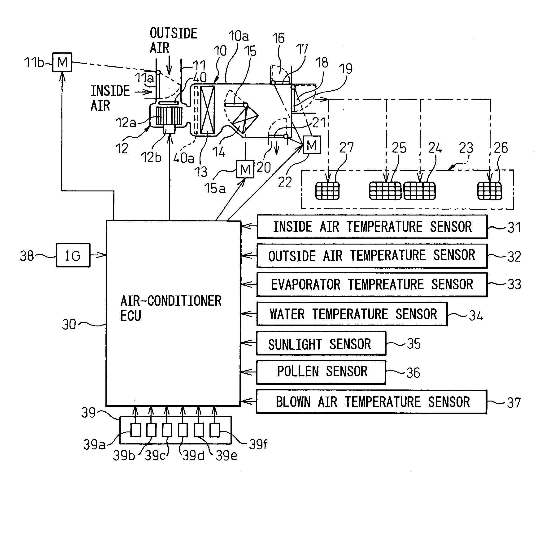
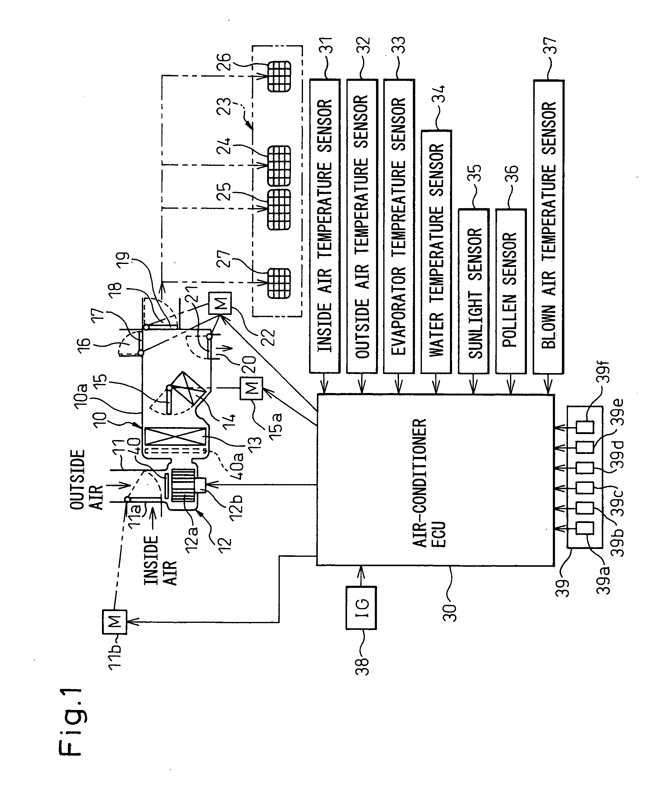
[0078] The second embodiment of the present invention does not make the blown air flow at the time of the start of the pollen mode the flat limit maximum air flow M1 like in the first embodiment, but adjusts it in accordance with the blown air temperature, in particular lowers the blown air flow when the blown air temperature is low. The point of difference from the first embodiment lies in the air-conditioner controller 30 only determines the instruction (blower air flow level) to be given to the motor 12b for driving the blower 12 using the detected temperature of the blown air temperature sensor 37. The rest of the configuration (FIG. 1 to FIG. 4) is similar to the first embodiment. Therefore, below, only the point of difference will be explained.

[0079]FIG. 8 is a view of the control characteristics of the pollen mode in the second embodiment. In the same way as the first embodiment, as the ignition switch 38 is turned on, the pollen mode is started, whereupon the intake mode is...

third embodiment

[0082] The third embodiment does not make the blown air flow in a predetermined period after the start of the pollen mode a constant limit maximum air flow M1, but performs intermittent control so as to switch the blown air flow between the limit maximum air flow M1 and a first air flow smaller than the limit maximum air flow M1. The point of difference from the first embodiment lies only in the intermittent fluctuation of the level of the blower air flow used as the instruction given to the motor 12b for driving the blower 12 serving as the blower control means by the air-conditioner controller 30. The rest of the configuration (FIG. 1 to FIG. 4) is similar to the first embodiment. Therefore, only the points of difference will be explained below.

[0083]FIG. 9 is a view of the control characteristics of the pollen mode in the third embodiment. That is, in the third embodiment, when the ignition switch 38 is turned on and the pollen mode is started, the blown air flow from the face v...

fourth embodiment

[0086] The fourth embodiment does not intermittently change the level of the blower air flow of the blower 12 like in the third embodiment, but switches the vents, that is, switches between the face vent and other vents such as the foot vent so as to substantively intermittently change the blown air flow from the face vent. Therefore, the point of difference from the first embodiment lies only in the air-conditioner controller 30 giving instructions to the actuator 22 for driving the doors 17, 19, and 21 serving as the vent control means in the pollen mode. The rest of the configuration (FIG. 1 to FIG. 4) is similar to the first embodiment. Therefore, only the points of difference will be explained below.

[0087]FIG. 10 is a view of the control characteristics of the pollen mode in the fourth embodiment. That is, in the fourth embodiment, when the ignition switch 38 is turned on and the pollen mode is started, the vent mode is switched between the face mode and the foot mode for exam...


PUM

PropertyMeasurementUnit
Temperatureaaaaaaaaaa
Timeaaaaaaaaaa
Flow rateaaaaaaaaaa

Abstract

A vehicular air-conditioner with a pollen mode setting intake to an inside air mode, vents to a face mode, and a blower air flow to a limit maximum air flow M1 between a minimum air flow Lo and a maximum air flow Hi (Lo<M1<M2<Hi), with an air-conditioning unit provided with a filter for trapping pollen and blowing clean air from which pollen has been removed from the vents to the vehicle compartment, whereby by starting the pollen mode simultaneously with the start of the engine, clean air is immediately blown to the vicinity of the face of the driver from the face vents and thereby the pollen entering the vehicle or pollen carried into the vehicle in the vicinity of the face is blown away, the air flow at this time being a maximum air flow M1 able to be withstood in terms of temperature sensation, so a pollen free comfortable environment being created without causing discomfort.

Description

BACKGROUND OF THE INVENTION [0001] 1. Field of the Invention [0002] The present invention relates to a vehicular air-conditioner, more particularly relates to a vehicular air-conditioner able to reduce the effect of pollen on the driver so as to improve comfort. [0003] 2. Description of the Related Art [0004] In recent vehicular air-conditioners, the flow of the air-conditioning air is mainly being controlled taking into consideration the sensation of temperature so as to realize comfort in the vehicle compartment (for example, see Japanese Patent No. 3430562). [0005] Demands on air-conditioning comfort are becoming tougher. In particular, there is a growing need for taking the health of the driver into consideration, such as by removing pollen. As a system for this, a vehicular air-conditioner providing a pollen filter only in the outside air duct to remove the pollen from the outside air before blowing it into the vehicle compartment has been proposed (for example, see Japanese Un...

Claims


Application Information

Patent Timeline
IPC IPC(8): B60H1/00B60H3/00B60H3/06
CPCB60H3/0608B60H1/00842
Inventor SASSA, YUKIYAKATO, KENICHIKATO, YASUSHITAKEDA, HIRONOBU
Owner DENSO CORP
Learn More