Intake system for internal combustion engine and method of controlling internal combustion engine

a technology of internal combustion engine and intake system, which is applied in the direction of combustion engine, charge feed system, air cleaner for fuel, etc., can solve the problems of inability to accurately recognize, inability to accurately control the amount of fuel injected into the cylinder, and relatively high cost of the overall intake system including the measuring unit, so as to increase the accuracy of controlling the operation of the internal combustion engine. , the effect of high accuracy

Inactive Publication Date: 2005-10-27
KEIHIN CORP
View PDF5 Cites 9 Cited by
  • Summary
  • Abstract
  • Description
  • Claims
  • Application Information

AI Technical Summary

Benefits of technology

[0014] It is a general object of the present invention to provide an intake system for use in an internal combustion engine, which detects an amount of intake air drawn into the internal combustion engine with increased accuracy and controls operation of the internal combustion engine highly accurately, and a method of controlling operation of an internal combustion engine.

Problems solved by technology

Consequently, the control circuit fails to accurately recognize the amount of intake air actually introduced into the cylinders, and is unable to accurately control the amount of fuel injected into the cylinders based on the amount of intake air.
Furthermore, since the detector, such as a pressure sensor or the like, is required for estimating the amount of intake air that fills the intake manifold, the cost of the overall intake system including the measuring units is relatively high.
According to the above conventional intake systems, when the throttle valve is opened and closed, the flow of intake air downstream of the throttle valve tends to be disturbed, making it difficult for the sensor disposed downstream of the throttle valve to measure the amount of intake air accurately.
While the internal combustion engine is in operation, unburned gases produced in the combustion chambers thereof are liable to find their way through the intake ports and flow into the intake manifold downstream of the throttle valve when the intake valves are opened.
Therefore, the detecting element of the sensor disposed downstream of the throttle valve may become contaminated by the unburned gases and the recirculated exhaust gases, tending to lower the detection accuracy of the sensor.

Method used


Image

  • Intake system for internal combustion engine and method of controlling internal combustion engine
  • Intake system for internal combustion engine and method of controlling internal combustion engine
  • Intake system for internal combustion engine and method of controlling internal combustion engine

Examples


first embodiment

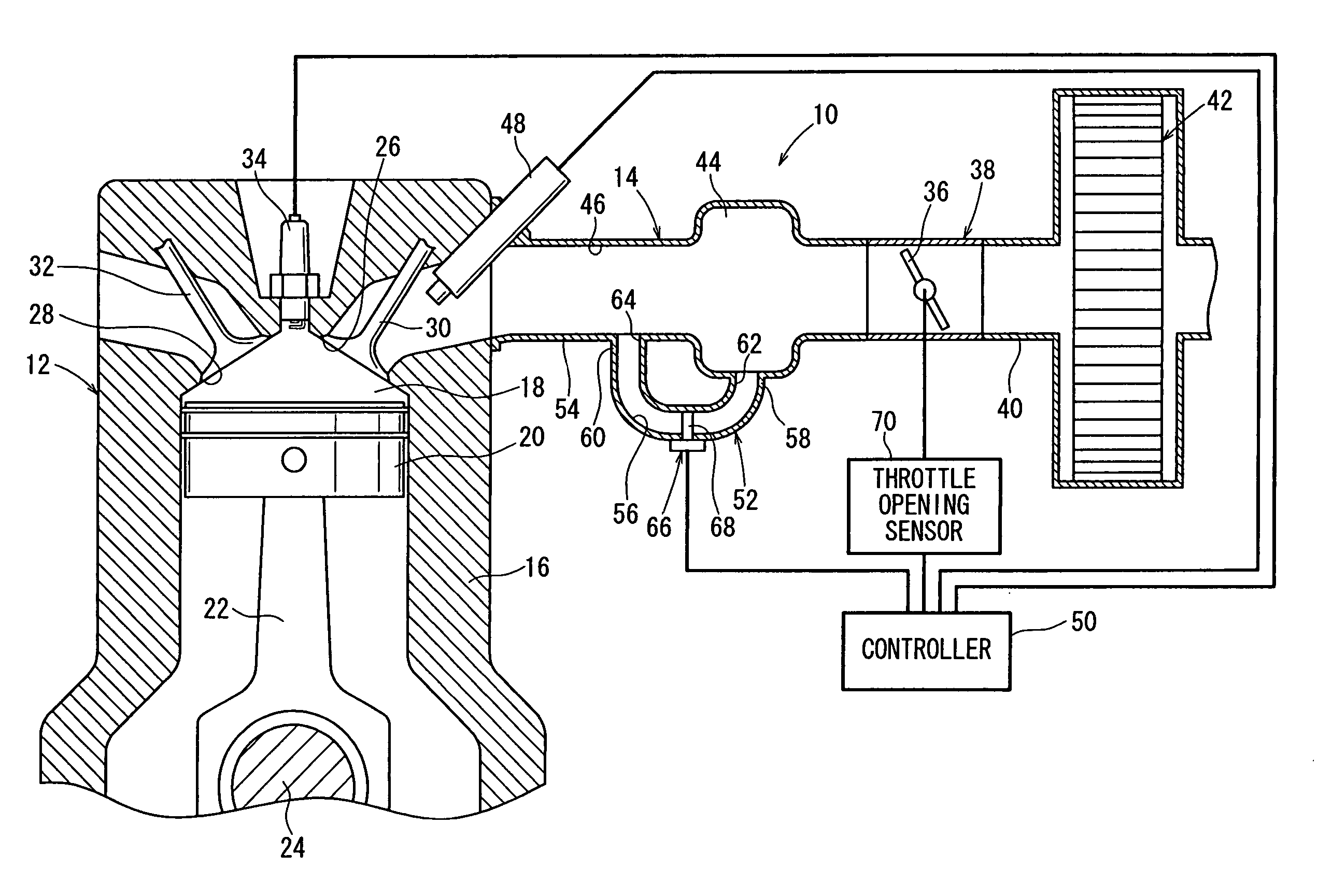
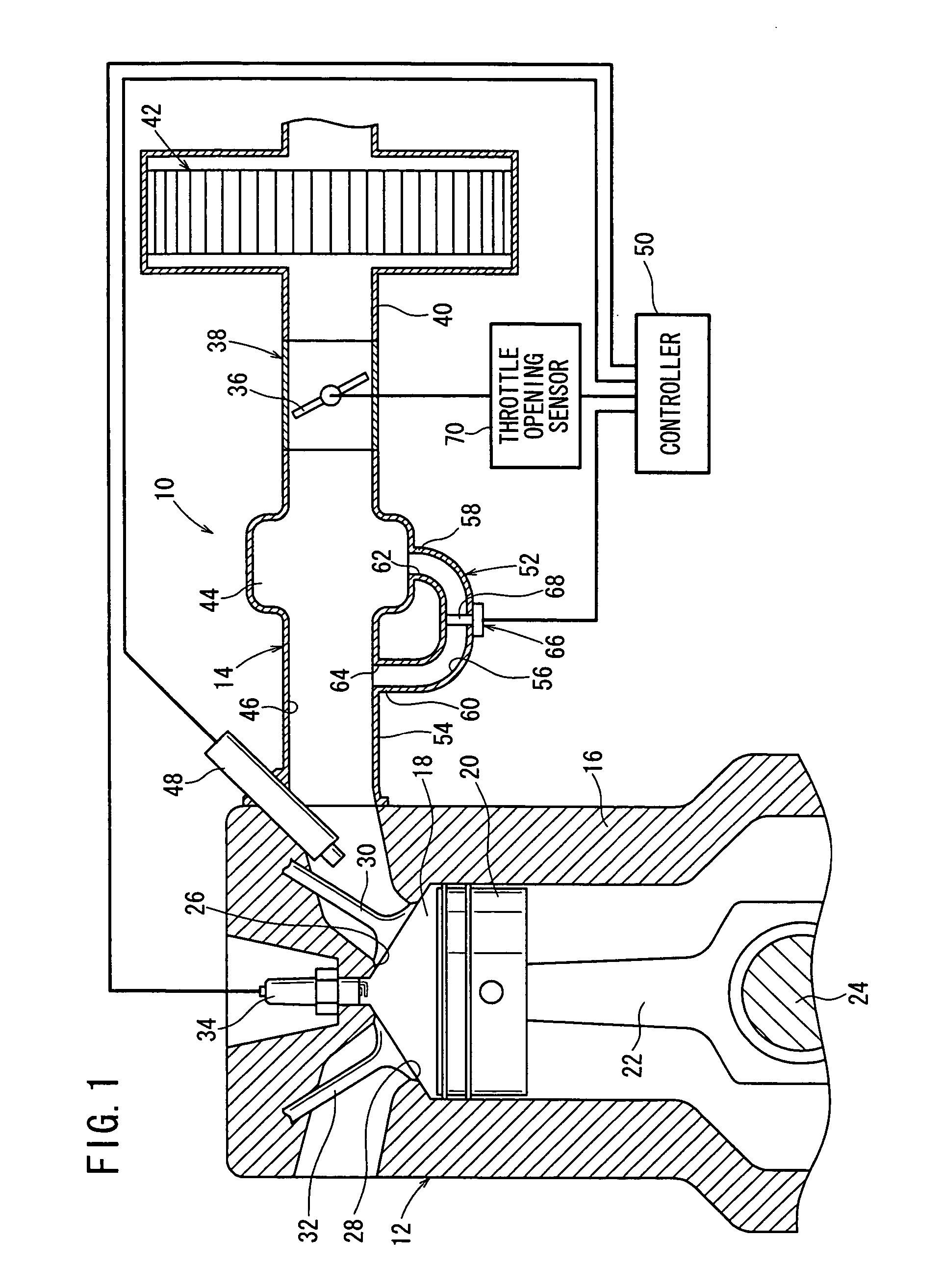
[0034]FIG. 1 shows an intake system 10 for an internal combustion engine according to the present invention. A method of controlling operation of an internal combustion engine according to the present invention is applied to the intake system 10.

[0035] The intake system 10 is combined with an engine (internal combustion engine) 12 for use on a motor vehicle or the like. In addition to having its own capability to introduce intake air into the engine 12, the intake system 10 serves to measure an amount of intake air drawn into the engine 12. The motor vehicle on which the intake system 10 is installed may be an automobile, a motorcycle, or the like.

[0036] As shown in FIG. 1, the engine 12 has a plurality of cylinder chambers 18 (one shown) defined in an engine body 16, and a plurality of pistons 20 (one shown) axially displaceably disposed in the cylinder chamber 18. When the piston 20 is displaced in its stroke, it changes the volume of the cylinder chamber 18 to cause the engine 1...

second embodiment

[0099] The intake system 200 according to the present invention, to which the method of controlling the intake system according to the present invention is applied, is basically constructed as described above. Control operations and advantages of the intake system 200 will be described below.

[0100] With the engine 204 started, the driver of the motor vehicle depresses the accelerator pedal (not shown) to open the throttle valve 36, lifting the intake valves 30 off the valve seats in the intake ports 26. Therefore, in the intake stroke, when the first through fourth pistons 208a through 208d are successively displaced downwardly, intake air is introduced from the air cleaner 42 (see FIG. 6) into the intake manifold 210, under an intake negative pressure developed in the first through fourth cylinder chambers 202a through 202d.

[0101] A portion of the intake air that is introduced through the throttle valve 36 into the intake passage 216 is introduced through the tank 44 from the firs...

third embodiment

[0160] the air flow meter 66 is spaced from the first and second connecting ends 230, 232 by the respective distances L1, L2, as described above. Since the flow of intake air flowing into the bypass pipe 302 from the first connecting end 230 thereof, and the flow of intake air flowing into the bypass pipe 302 from the second connecting end 232 thereof, cancel each other in a substantially central portion within the bypass pipe 302, the air flow meter 66 does not detect an amount of intake air flowing through the bypass pipe 302 that is subjected to intake air flow pulsations, but rather, only detects an amount of intake air flowing through the bypass pipe 302 from the first connecting end 230 to the second connecting end 232.

[0161] Operations and advantages of the intake system 300, for drawing intake air into the second cylinder C2, shall be described below.

[0162]FIG. 17 shows characteristic curves representing respective amounts Q of intake air, plotted against time, that are dr...


PUM


Abstract

An intake system has a tubular intake manifold, having an end connected to an intake port of an engine and an opposite end connected to a throttle body that includes a throttle valve. The intake system also has a bypass passage, connected to the intake manifold downstream of the throttle valve, and an air flow meter disposed in the bypass passage for detecting an amount of intake air drawn into the engine. A portion of the intake air that flows through the intake manifold is divided and flows into the bypass passage, wherein the amount of intake air flowing through the bypass passage is detected by the air flow meter.

Description

BACKGROUND OF THE INVENTION [0001] 1. Field of the Invention [0002] The present invention relates to an intake system for use in an internal combustion engine, which measures an amount of intake air drawn into the internal combustion engine and controls operation of the internal combustion engine based on the measured amount of intake air, and a method of controlling operation of an internal combustion engine. [0003] 2. Description of the Related Art [0004] Internal combustion engines that have heretofore been used on motor vehicles or the like have an intake manifold for introducing intake air into the cylinders which provide combustion chambers and intake valves mounted in respective intake ports, to which the intake manifold is connected, for selectively bringing the cylinders into and out of communication with the intake manifold. When the intake valves are opened, intake air is introduced through the intake manifold into the cylinders. [0005] The intake manifold houses therein ...

Claims


Application Information

Patent Timeline
Patent Type & Authority Applications(United States)
IPC IPC(8): F02M35/04F02M35/10
CPCF02M35/021F02M35/10131F02M35/108F02M35/10386F02M35/10308F02M35/112
Inventor SHIMATSU, TAKAYUKI
Owner KEIHIN CORP
Why Eureka
Try Eureka