Method and apparatus for performing bistatic radar functions

Inactive Publication Date: 2005-10-27
BUDIC ROBERT D
View PDF7 Cites 61 Cited by
  • Summary
  • Abstract
  • Description
  • Claims
  • Application Information

AI Technical Summary

Benefits of technology

[0087] Another embedment of the invention comprises a method of filtering and processing a received radar signal comprising the steps of: receiving an element-level radar signal; splitting the element-level radar signal into a plurality of signal components, each signal component comprising energy scattered by

Problems solved by technology

The clutter signal is treated as one type of interference that degrades radar system performance.
A third type of interference is due to transmitters that operate either intentionally or unintentionally at or near the radar center frequency.
In monostatic airborne and space borne radar systems, ground clutter is a greater challenge primarily because it is spread throughout a large region of the delay and Doppler measurement space.
DPCA sensor and processing parameters do not depend on the clutter environment and in this sense are non-adaptive or deterministic.
The computational complexity is typically dominated by the need to d

Method used


Image

  • Method and apparatus for performing bistatic radar functions
  • Method and apparatus for performing bistatic radar functions
  • Method and apparatus for performing bistatic radar functions

Examples


Embodiment Construction

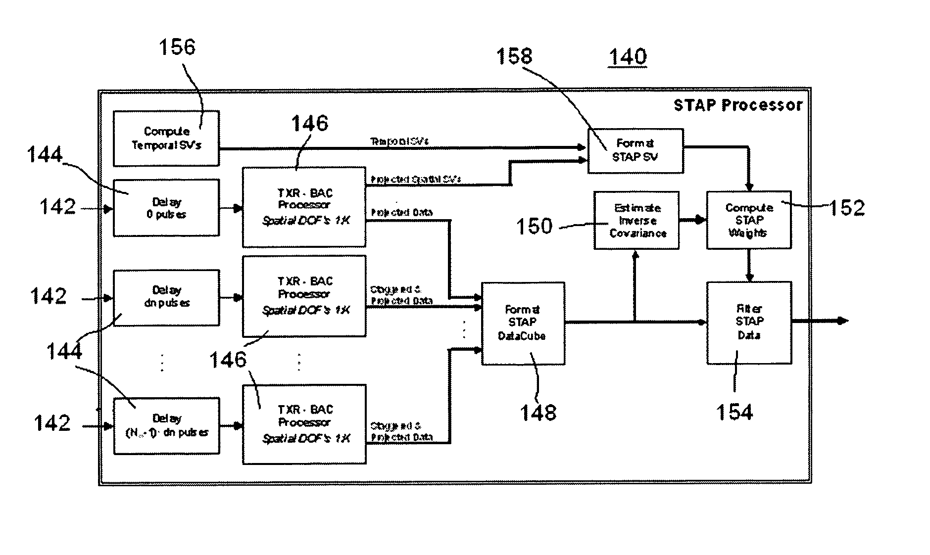
[0108] The present invention of distributed bistatic apertures builds on basic principles and reformulates the bistatic clutter suppression problem in a way that desirable features of monostatic operation, linearity and delay-independence, re-emerge. In particular, this new approach begins with the observation that the temporal clutter signature, the Doppler shift, is inherently distributed in space-time in the sense that it is depends on a combination of transmitter and receiver motion and position of the clutter patch relative to both the transmitter and receiver. This being the case, a simplified linear coupling with angle measurements will emerge only when the bistatic aperture is expanded to include transmitter degrees of freedom. When this is accomplished, the angle measurements, measurements of the spatial signature (i.e., sensor DOF's), are also distributed and more naturally matched to the observed Doppler effects.

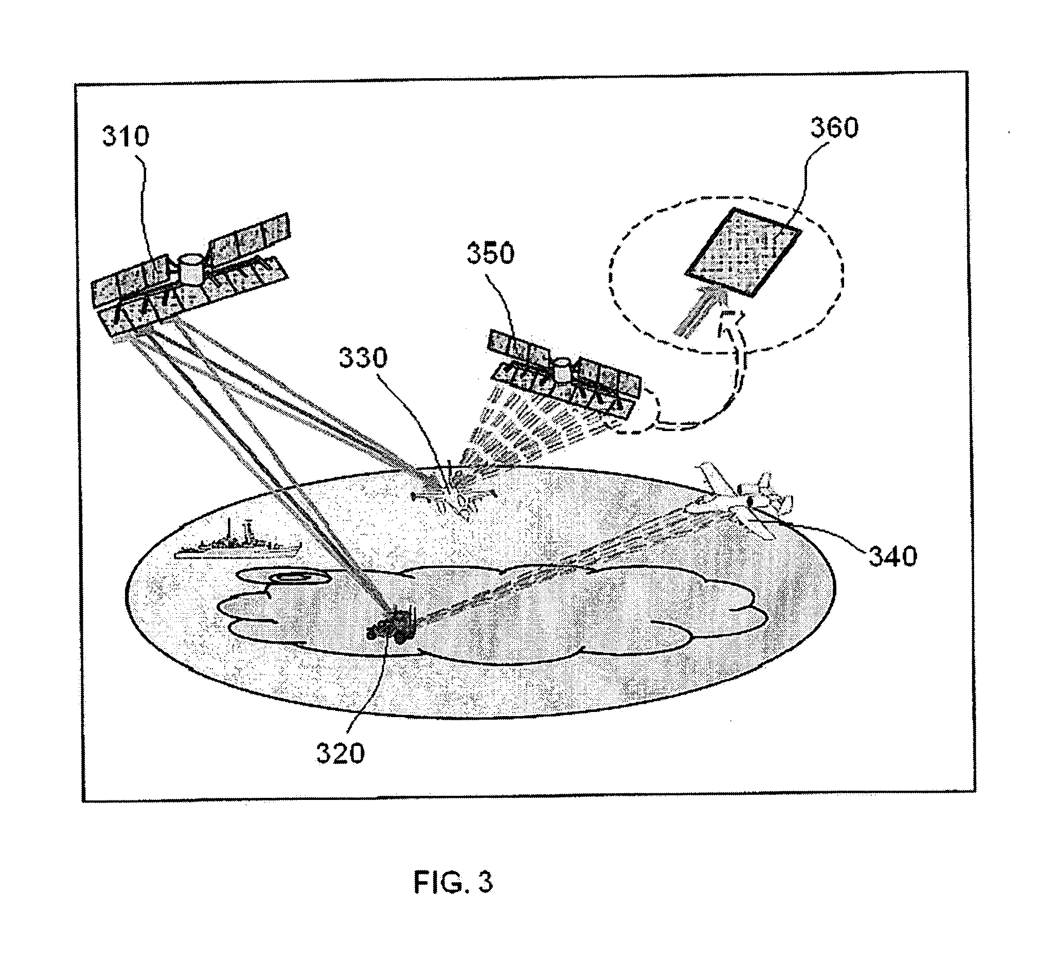
[0109]FIG. 3 depicts an example of an environment of an ada...


PUM


Abstract

A bistatic radar system having a transmitter that generates unique signals at spatially independent transmitter degrees of freedom and a receiver that filters the signal at each receiver degree of freedom into a group of signals identical in number to the number of transmitter degrees of freedom. The receiver formats the filtered signals into a 2-dimensional array of elements. The receiver rotates the array so that the new axes are aligned with the Doppler gradient. The data is then re-sampled and projected to linearize the clutter signal. The receiver may be integrated with a broad class of adaptive and non-adaptive clutter mitigation approaches such as electronic clutter tuning and projected bistatic space-time adaptive processing, or STAP.

Description

CROSS-REFERENCE TO RELATED APPLICATIONS [0001] This application claims the benefit of U.S. Provisional Application Ser. No. 60 / 565,376 filed on Apr. 26, 2004 by inventor Robert Budic. [0002] Other related patent applications include the following: [0003]“Adaptive Broadcast Radar,” U.S. Provisional Application Ser. No. 60 / 253,095; Filed on Nov. 28, 2000; Inventor: Robert D. Budic. [0004]“System and Method for Adaptive Broadcast Radar System,” U.S. Pat. No. 6,861,976, issued Mar. 1, 2005; Inventor: Robert D. Budic. [0005] The entirety of each of the aforementioned patent applications is incorporated by reference herein.STATEMENT REGARDNING FEDERALLY SPONSORED RESEARCH OR DEVELOPMENT [0006] Not applicable. BACKGROUND OF THE INVENTION [0007] 1. Field of the Invention [0008] This invention relates to techniques for performing bistatic radar functions when a transmitter platform is in motion. [0009] 2. Brief Description of the Related Art [0010] Radar systems may be monostatic, bistatic o...

Claims


Application Information

Patent Timeline
IPC IPC(8): G01S7/36G01S7/41G01S13/00G01S13/22G01S13/28G01S13/524
CPCG01S7/36G01S7/414G01S13/5244G01S13/225G01S13/284G01S13/003
Inventor BUDIC, ROBERT D.
Owner BUDIC ROBERT D
Why Eureka
Try Eureka