Switched multi-beam antenna

a multi-beam antenna and switch technology, applied in the direction of resonant antennas, differential interacting antenna combinations, independent non-interacting antenna combinations, etc., can solve the problems of high cost, excessive loss of electronic scanning technologies, and many wireless communication systems of today's wireless communication systems provide very little room for antennae elements, reflectors and directors, to achieve the effect of minimizing losses

Inactive Publication Date: 2005-10-27
AIRGAIN INC
View PDF18 Cites 285 Cited by
  • Summary
  • Abstract
  • Description
  • Claims
  • Application Information

AI Technical Summary

Benefits of technology

[0009] A further aspect of the invention is a method of manufacturing an antenna assembly including providing a base layer having an upper surface and a lower surface; forming a primary reflective surface on the base layer; providing a plurality of antenna elements proximate the upper surface of the base layer; providing one or more reflectors proximate the upper surface of the base layer positioned to operate as a reflector for each of the plurality of antenna elements and electrically coupling the one or more reflectors to the primary reflective surface; and coupling a switch, configured to select an active state or inactive state for each of the plurality of antenna elements in response to a control signal, to each of the plurality of antenna elements. The method can further include matching the impedance of each of the plurality of antenna elements to the switch to minimize losses. Alternatively, The method can include adjusting the impedance of each of the plurality of antenna elements with respect to the switch such that the mismatch loss is equal for the cases when one of the plurality of antenna elements in the active state and when two of the plurality of antenna elements are in the active state. The impedance of an antenna element can be adjusted by shorting one or more impedance tuning pads to the antenna element. In addition, one or more impedance tuning pads can be shorted to each other.

Problems solved by technology

However, many such electronic scanning technologies are plagued with excessive loss and high cost.
In addition, many of today's wireless communication systems provide very little room for antennae elements.
The reflector and directors are not driven, and are therefore parasitic elements.

Method used


Image

  • Switched multi-beam antenna
  • Switched multi-beam antenna
  • Switched multi-beam antenna

Examples


Embodiment Construction

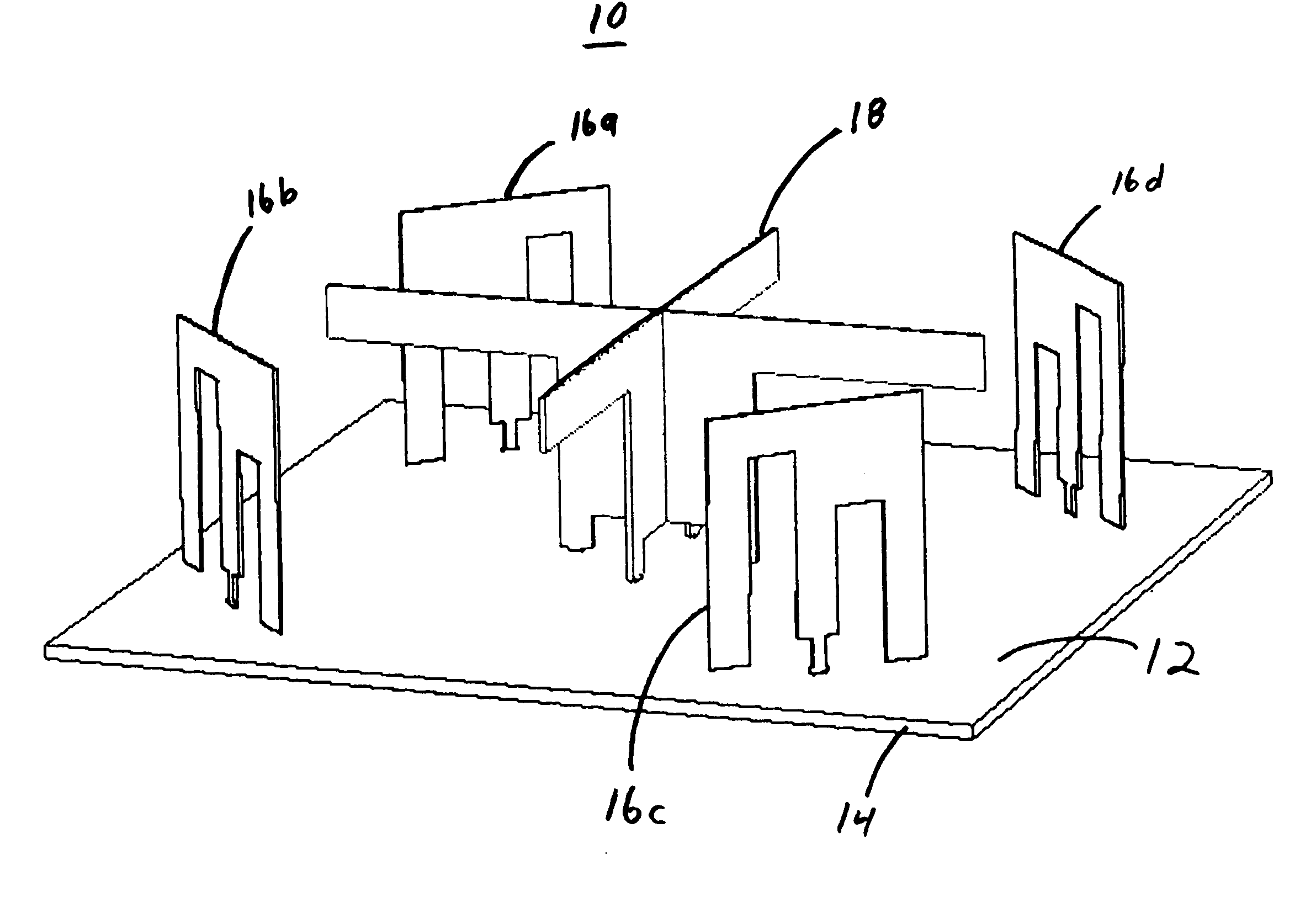
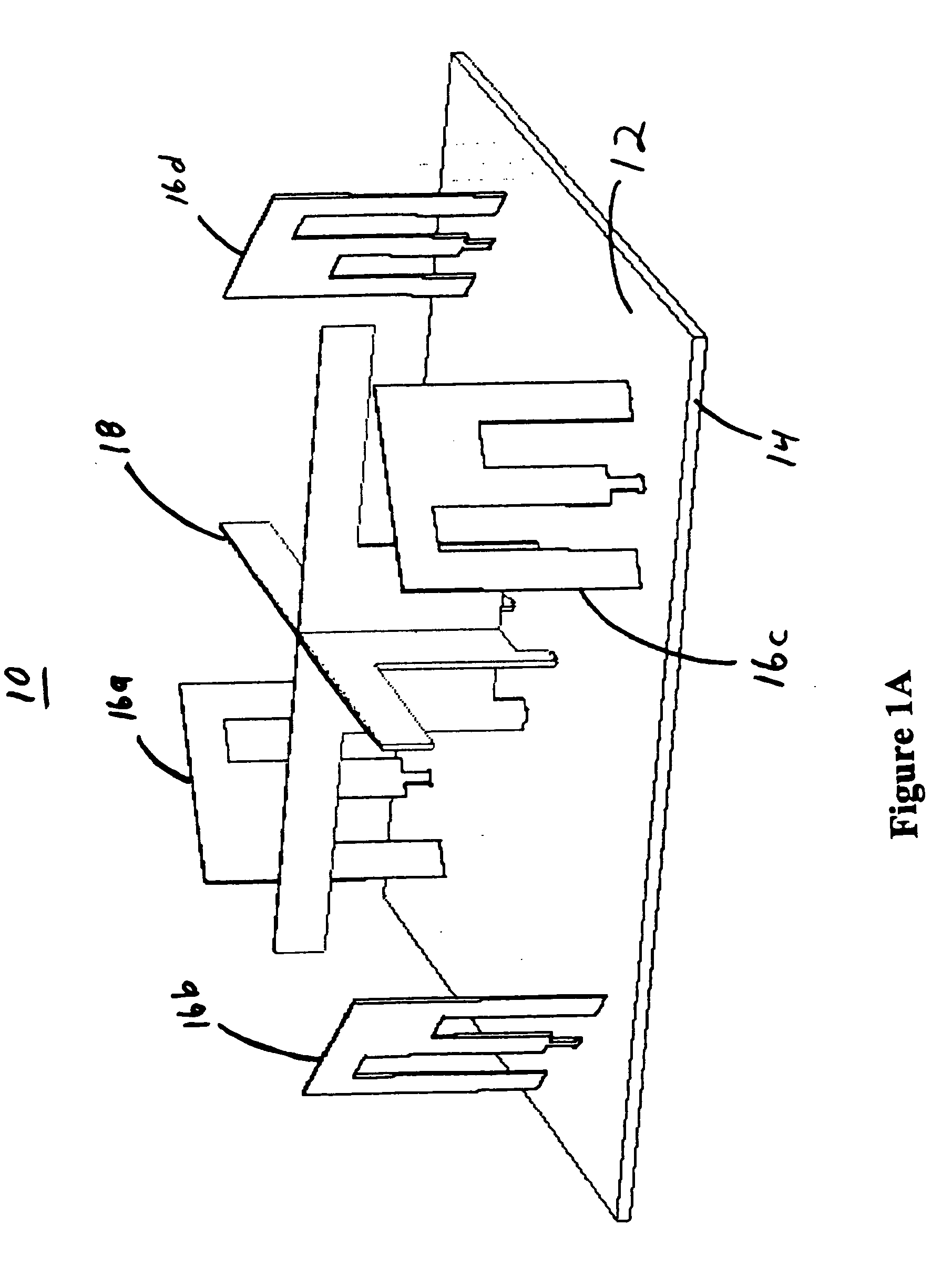
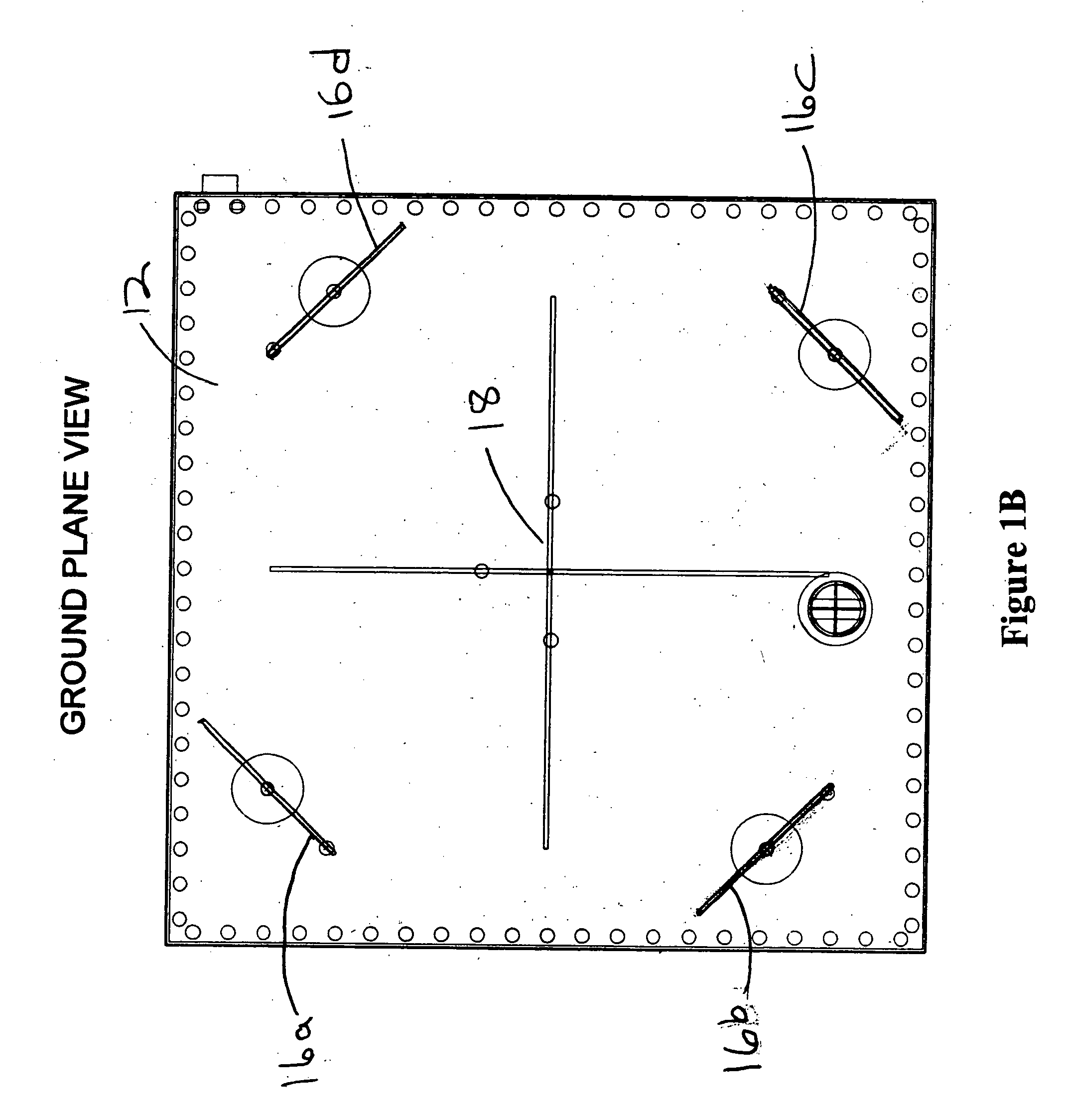
[0020] Certain embodiments as disclosed herein provide for systems and methods for a wireless communication device or system having a switched multi-beam antenna and methods for manufacturing the same. For example, one system and method described herein provides for a plurality of monopole antenna elements mounted on a reflective surface. A common reflector cooperates with each active antenna element to create a directed transmission or a direction of positive gain. A switch allows for activating one or more of the antenna elements to vary the direction of the transmission. All of the antenna elements can be activated to cause the antenna assembly to transmit omni-directionally. Directors above or below the reflective surface can be used to modify the characteristics of the antenna. The system can be used with various wireless communication protocols and at various frequency ranges. For example, the system can be used at frequency ranges including 2.4, Giga hertz, 2.8 Giga hertz, an...


PUM


Abstract

An antenna assembly includes a common reflector and multiple monopole type antenna elements positioned on a ground plane and fed with a switch assembly. The switch assembly is capable of feeding individual antennas as well as combining multiple antennas for improved radiation pattern coverage. Multiple antenna elements are placed around the common reflector to cover sectors of space around the antenna assembly to provide transmission and reception of radio frequency (RF) signals for mobile communication devices in a wireless network. The ground plane can be grounded or capacitively coupled to an existing circuit board or metal surface, allowing for reduced ground plane dimensions.

Description

RELATED APPLICATIONS [0001] This application claims the benefit of U.S. Provisional Application No. 60 / 562,097 filed Apr. 12, 2004, entitled MONOPOLE YAGI ANTENNA ARRAYS UTILIZING A COMMON REFLECTOR and is a Continuation-in-Part of U.S. application Ser. No. 10 / 510,157, filed Sep. 27, 2004, titled: AN ANTENNA SYSTEM WITH A CONTROLLED DIRECTIONAL PATTERN, A TRANSCEIVER AND A NETWORK PORTABLE COMPUTER (which claimed the benefit of PCT / RU03 / 00119 filed Mar. 24, 2003 and Russian application 2002108661 filed Mar. 27, 2002). Each of the foregoing applications are hereby incorporated by reference.FIELD OF THE INVENTION [0002] This invention relates to wireless communication systems including direction-agile antennas useful in such systems. BACKGROUND OF THE INVENTION [0003] In wireless communication systems, antennas are used to transmit and receive radio frequency signals. In general, the antennas can be omni-directional or unidirectional. In addition, there exist antenna systems which pro...

Claims


Application Information

Patent Timeline
Patent Type & Authority Applications(United States)
IPC IPC(8): H01Q1/38H01Q3/24H01Q9/24H01Q9/32H01Q9/42H01Q19/10H01Q21/28H01Q21/29
CPCH01Q3/24H01Q3/242H01Q19/106H01Q9/42H01Q19/10H01Q9/32H01Q21/205
Inventor ABRAMOV, OLEG YURIEVICHROBISON, DAVID B.SHAMBLIN, JEFFREY K.NAGAEV, FARID IBRAGIMOVICHVISURI, PERTTI J.
Owner AIRGAIN INC
Why Eureka
Try Eureka