Miniature optical readhead for optical diagnostic device

a technology of optical diagnostic device and readhead, which is applied in the field of clinical chemistry, can solve the problems of inability to accurately measure, difficult to transport, and large volume of samples from multiple patients, and achieve the effect of aggregating samples from multiple patients and presenting opportunities for errors

Inactive Publication Date: 2005-10-27
SIEMENS HEALTHCARE DIAGNOSTICS INC
View PDF6 Cites 23 Cited by
  • Summary
  • Abstract
  • Description
  • Claims
  • Application Information

AI Technical Summary

Benefits of technology

[0015] A further aspect of the invention includes a method for reading reagent sample media, the sample media having a plurality of test areas disposed in spaced relation thereon, each of the test areas configured to react with a sample when disposed in contact with the sample and to change color according to an amount of an analyte in the sample. The method includes receiving the sample media into a sample holder of a readhead of a photometric diagnostic device, the readhead having a hand-held form factor, and the sample holder configured to maintain the sample m

Problems solved by technology

Color comparisons made with the naked eye can lead to imprecise measurement.
A common aspect of these instruments is that their relative size and complexity, particularly with respect to those utilizing automated test pad transport systems, render them relatively bulky and difficult to transport.
Unfortunately, such aggregation of samples from multiple patients presents opportunities for error due to mislabeling of the samples and/or the test results.

Method used


Image

  • Miniature optical readhead for optical diagnostic device
  • Miniature optical readhead for optical diagnostic device
  • Miniature optical readhead for optical diagnostic device

Examples


example

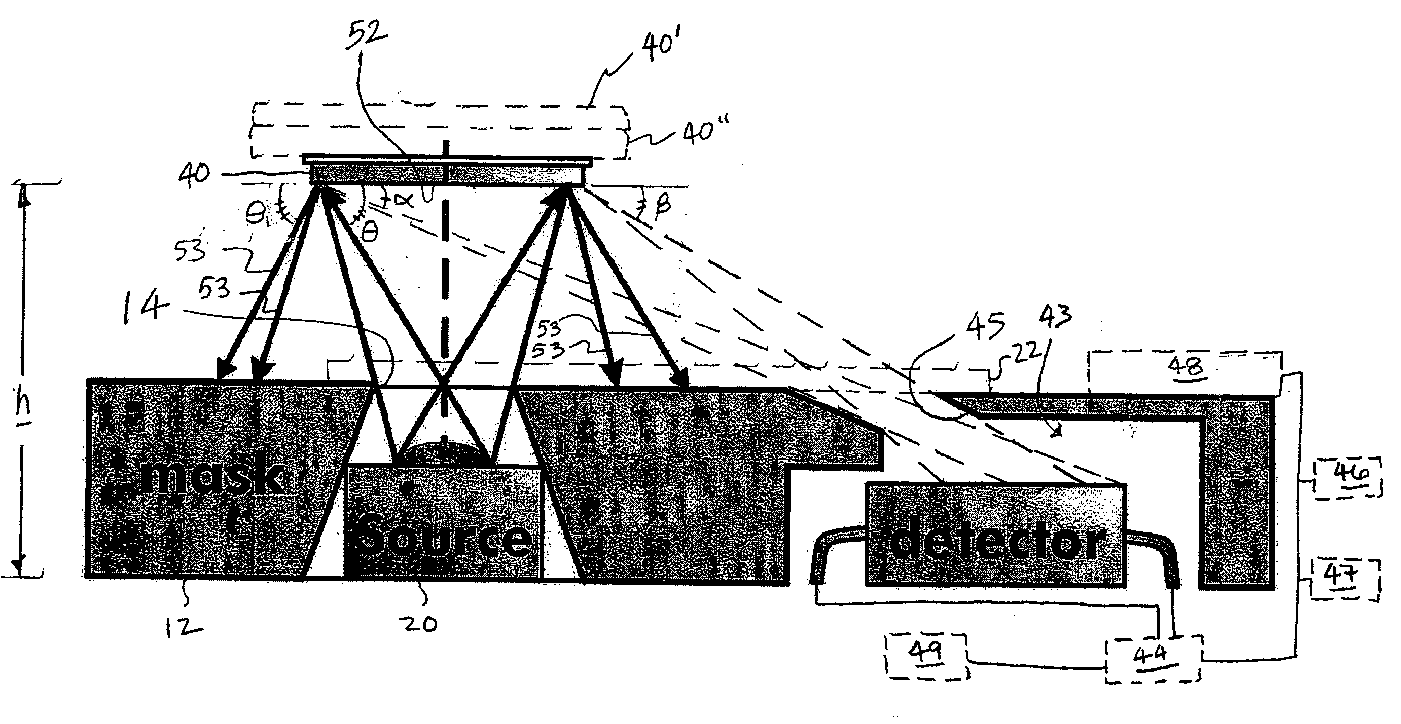
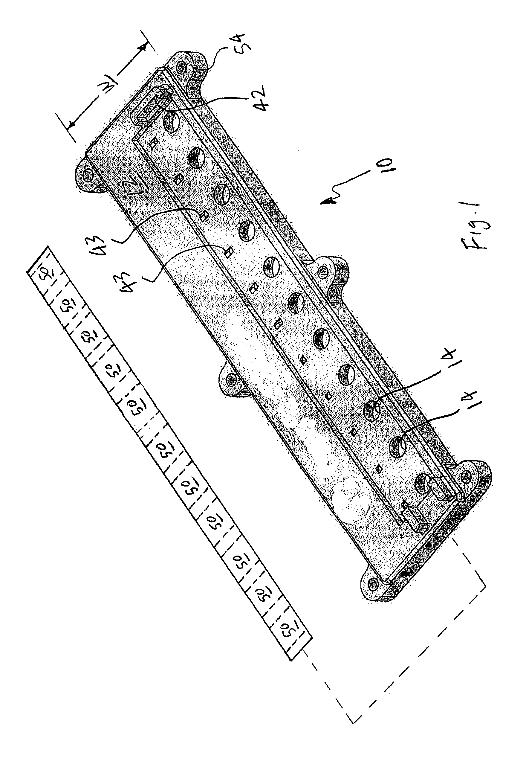
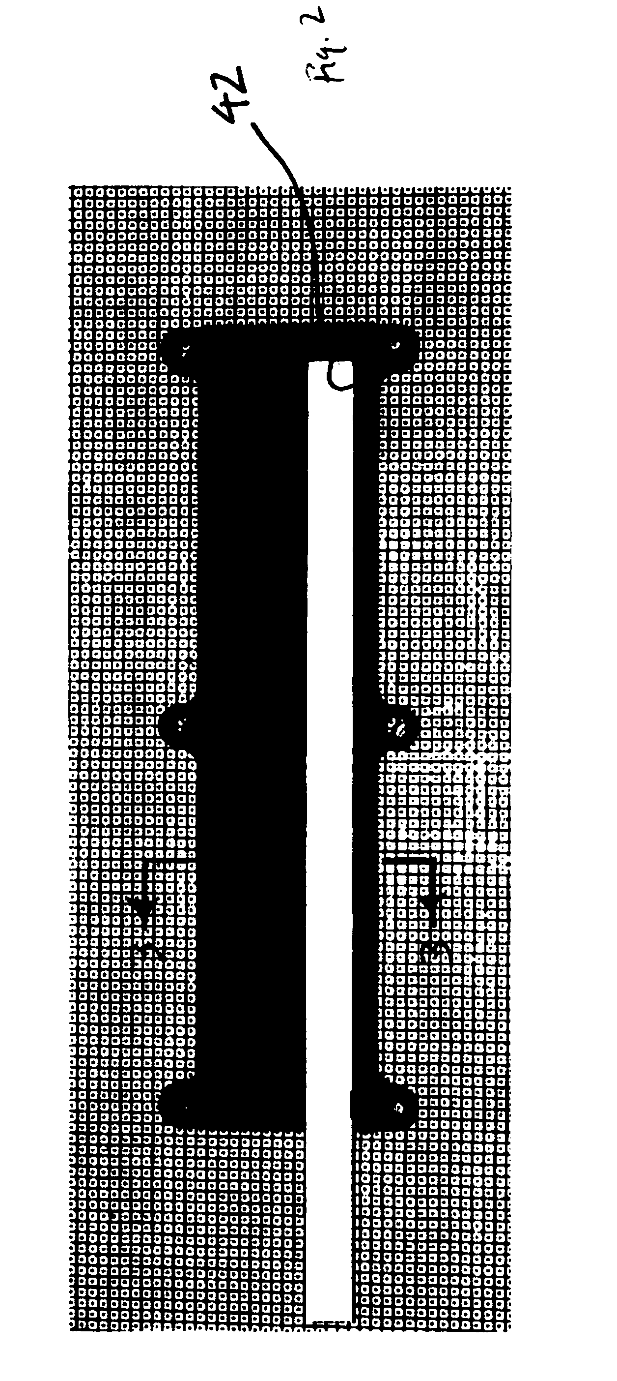
[0060] A readhead 10 was fabricated substantially as shown and described hereinabove with respect to FIGS. 1-4. Housing 12 was injection molded with dimensions of 5×12×82 mm, with a sample holder 42 configured to receive a MULTISTIX® (Bayer) test strip 40. Housing 12 was fitted with an array of eleven RGB LEDs 20. An array of eleven chambers 43 were fabricated with shielding 45 substantially as shown and described. A TCS230 (TAOS, Inc.) pixilated color detector having an active area of 1.15×1.15 mm, was installed within each chamber 43. The LEDs 20 were disposed to provide illumination at an angle of incidence of approximately 90 degrees relative to a test strip 40 disposed within holder 42. Chambers 43 and color detectors 70 were configured to receive reflected light at angles of reflectance between approximately 10 and 30 degrees relative to strip 40. This readhead was tested and found to successfully generate similar performance to that of conventional instruments of larger form ...


PUM


Abstract

A miniature readhead for a photometric diagnostic instrument includes a housing of hand-held form factor, configured for receiving reagent sample media therein. The sample media has a plurality of test areas configured to react with, and change color, according to an amount of an analyte in a sample. The holder is sized and shaped for forming an indexed fit with the sample media and includes an array of light sources coupled to the housing, each of the light sources configured to emit light onto a respective one of the test areas. An array of chambers respectively containing an array of light detectors, is configured to enable each of the light detectors to receive diffuse, non-specular reflections of the light from the test areas, while substantially preventing the light detectors from receiving specular reflections of the light.

Description

RELATED APPLICATIONS [0001] This application is a Continuation-In-Part of co-pending P.C.T. Patent Application No. US05 / 07227, designating the United States, entitled Handheld Optical Diagnostic Device Having Image System Array, filed Mar. 3, 2005, which claims priority to U.S. Provisional Patent Application Ser. No. 60 / 550,811, entitled Handheld Optical Diagnostic Device Having Image System Array, filed on Mar. 5, 2004.BACKGROUND [0002] 1. Technical Field [0003] The present invention generally relates to the field of clinical chemistry. More particularly, the present invention relates to a readhead for an optical diagnostic system that analyzes the color change associated with one or more test areas on sample media following contact thereof with a liquid specimen, such as urine or blood. [0004] 2. Background Information [0005] Throughout this application, various patents are referred to by an identifying citation. The disclosures of the patents referenced in this application are he...

Claims


Application Information

Patent Timeline
IPC IPC(8): G01N21/27G01N21/47G01N21/86G06K9/00
CPCG01N21/253G01N21/474G01N21/4785G01N2201/064G01N21/8483G01N2201/0221G01N2201/0222G01N21/78
Inventor ROMAN, JUAN F.
Owner SIEMENS HEALTHCARE DIAGNOSTICS INC
Why Eureka
Try Eureka