Fan-shaped heat-dissipating device

a heat dissipation device and fan-shaped technology, which is applied in the direction of lighting and heating apparatus, instruments, and semiconductor/solid-state device details, etc., can solve the problems of components running the risk of damage, the temperature of the chip usually exceeds the load range, and the information product chip produces a lot of heat, so as to increase the dissipation effect of heat airflow and smooth heat airflow

Active Publication Date: 2005-10-27
VIA TECH INC
View PDF4 Cites 6 Cited by
  • Summary
  • Abstract
  • Description
  • Claims
  • Application Information

AI Technical Summary

Benefits of technology

[0010] A main object of the present invention is to provide a fan-shaped heat-dissipating device, applied on a chip of an erect PCB and having channels between the fins to enable smooth heat airflow for increasing a dissipation effect thereof.

Problems solved by technology

As the density of an IC (integrated circuit) increases, information product chip produces much heat, and the temperature of the chip usually exceeds the load range.
Without proper heat dissipation, the components run the risk of damage, to the point of interrupting even the host.
However, when the conventional heat-dissipating device is applied on a chip of an erect PCB, the heat of the chip is hard to dissipate.
The narrow intervals between the fins of the above heat-dissipating device cause the airflow to slow and decrease the dissipation effect.
Thus it can be seen that the above-mentioned heat-dissipating device obviously is inconvenient and suboptimal.

Method used


Image

  • Fan-shaped heat-dissipating device
  • Fan-shaped heat-dissipating device
  • Fan-shaped heat-dissipating device

Examples


Embodiment Construction

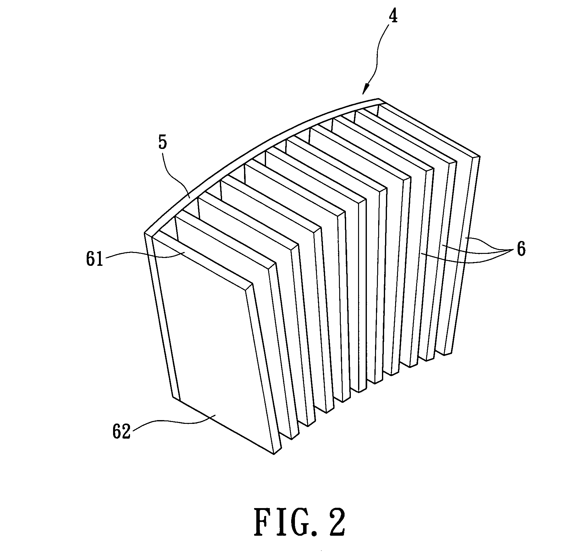
[0020]FIG. 2 is a schematic perspective view of a fan-shaped heat-dissipating device according to the present invention. A fan-shaped heat-dissipating device 4 of the present invention has a conductive board 5 and a plurality of fins 6. The conductive board 5 and the fins 6 are made of highly conductive material, such as alloy of aluminum, or copper, or both. The conductive board 5 leans against a heat source of an electric device. The fins 6 are connected erectly on an outside surface of the conductive board 5, respectively, and arranged in a radiating manner toward two sides from bottom ends to top ends thereof.

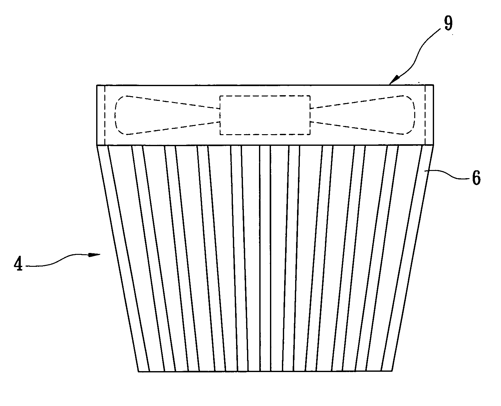
[0021] Reference is made simultaneously to FIG. 3, which is a schematic front view of the fan-shaped heat-dissipating device according to the present invention. Each of the fins 6 has an top end 61 and a bottom end 62, and an interval P1 of each two adjacent top ends 61 of the fins 6 is larger than an interval P2 of each two adjacent bottom ends 62 of the fins 6. The fins ...


PUM


Abstract

A fan-shaped dissipating device, which is assembled on a chip of an erect PCB, has a conductive board, and a plurality of fins. The fins are respectively connected on an outside surface of the conductive board. Each of the fins has a top end and a bottom end. An interval between each two adjacent top ends of the fins is larger that between each two adjacent bottom ends of the fins. The fins are arranged in a radiating manner toward two sides from the bottom ends to the upper ends, therefore reducing the density of the accumulated air between the top ends of the fins because of rising hot air, and providing a better dissipating effect.

Description

BACKGROUND OF THE INVENTION [0001] 1. Field of the Invention [0002] The present invention relates to a fan-shaped heat-dissipating device, and especially to a heat-dissipating device adapted to a chip of an erect PCB for heat dissipation. [0003] 2. Description of Prior Art [0004] As the density of an IC (integrated circuit) increases, information product chip produces much heat, and the temperature of the chip usually exceeds the load range. In particular, the operating speed and the processing function of the CPU (central processing unit) are increasing continually. Without proper heat dissipation, the components run the risk of damage, to the point of interrupting even the host. [0005] To solve the dissipation problem of the chip, a heat-dissipating device with multiple fins is usually mounted on the chip. The conventional art is shown in FIG. 1, which is a heat-dissipating device mounted on a chip of an erect PCB. The heat-dissipating device has a rectangular conductive board 1 a...

Claims


Application Information

Patent Timeline
Patent Type & Authority Applications(United States)
IPC IPC(8): F28F3/02G06F1/20H01L23/467H05K7/20
CPCF28F3/02H01L23/467H01L2924/0002H01L2924/00
Inventor LEE, I-TSENGKU, SHIH-CHANG
Owner VIA TECH INC
Why Eureka
Try Eureka