Thin-film magnetic head and manufacturing method thereof

a thin-film magnetic head and manufacturing method technology, applied in the field of thin-film magnetic head, can solve the problems of deterioration of reproduction properties, inability to efficiently discharge heat from the first shield layer b>31/b>, and insufficient heat transmission to the first shield layer, etc., to achieve excellent reproducibility and suppress the temperature rise of the thin-film magnetic head

Inactive Publication Date: 2007-09-20
TDK CORPARATION
View PDF1 Cites 2 Cited by
  • Summary
  • Abstract
  • Description
  • Claims
  • Application Information

AI Technical Summary

Benefits of technology

[0014] The present invention has been made in light of the above-described problems, and accordingly, it is an object thereof to provide a thin-film magnetic head and manufacturing method thereof for effectively reducing the distance between members having thermal dissipation capabilities and the substrate, to effectively improve thermal dissipation effects.

Problems solved by technology

The heat from each of these make the interior of the thin-film magnetic head hot, causing many problems such as leading to deterioration of reproduction properties by destroying the magnetoresistance effect element, causing the portion of the inductive head to protrude farther than the other portion due to difference in thermal expansion such that the thin-film magnetic head collides with the recording medium, and so forth.
The inorganic insulating film 710 is formed of Al2O3 or the like for example, but the thermal conductivity of Al2O3 is lower than that of metal film, so there is the problem that the heat transmitted to the first shield layer 31 cannot be efficiently discharged to the slider 73.
As a result, the heat remains within the thin-film magnetic head, making the inside of the thin-film magnetic head hot, and accordingly cannot effectively solve the above-described problems of reproduction properties and head damage.
Also, with the arrangement disclosed in Japanese Unexamined Patent Application Publication No. 2002-216314, the second shield film is formed extended long in the height direction in the same way as with the first shield film, but the entire second shield film is on an insulating layer covering the MR element, so the distance between the second shield film and the slider is even greater than that between the first shield film and the slider, so heat cannot be effectively discharged directly from the second shield film to the slider.
Accordingly, the heat absorbed by the second shield film passes through the first shield film and is indirectly discharged to the slider, but indirect discharge does not allow the heat absorbed by the second shield film to be more effectively transmitted, so there is the possibility that the heat may still remain within the second shield film.
Also, an electrode extracting layer for supplying detecting current to the magnetoresistance effect element is connected to the magnetoresistance effect element, so the position for forming the electrode extracting layer needs to be taken into consideration in order to effectively reduce the distance between the second shield film and the slider, but this electrode extracting layer is neither disclosed nor even suggested in Japanese Unexamined Patent Application Publication No. 2002-216314, and the above-described problem is similarly unsolved by the art disclosed in Japanese Unexamined Patent Application Publication No. 2001-236614.

Method used


Image

  • Thin-film magnetic head and manufacturing method thereof
  • Thin-film magnetic head and manufacturing method thereof
  • Thin-film magnetic head and manufacturing method thereof

Examples


first embodiment

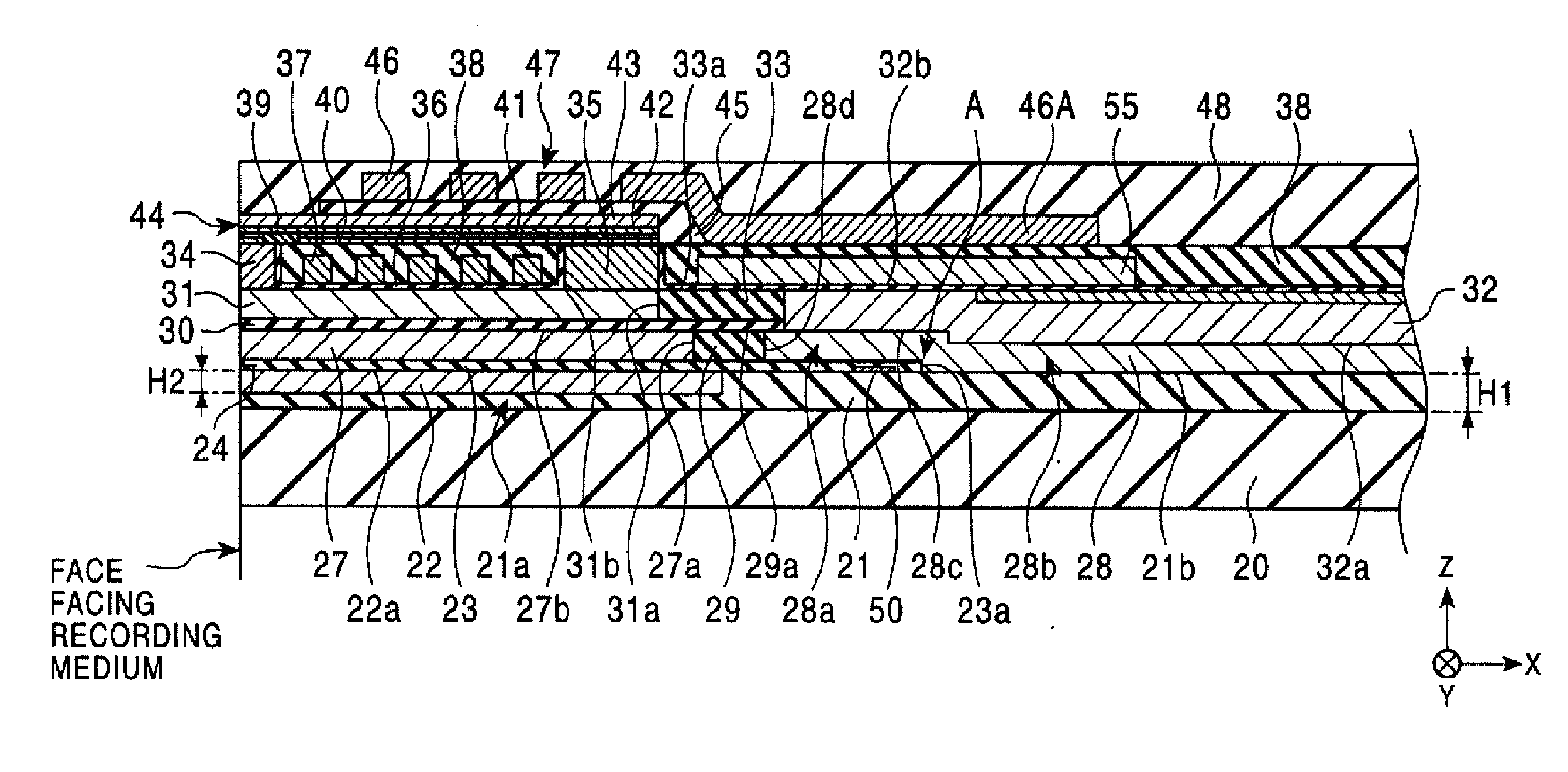
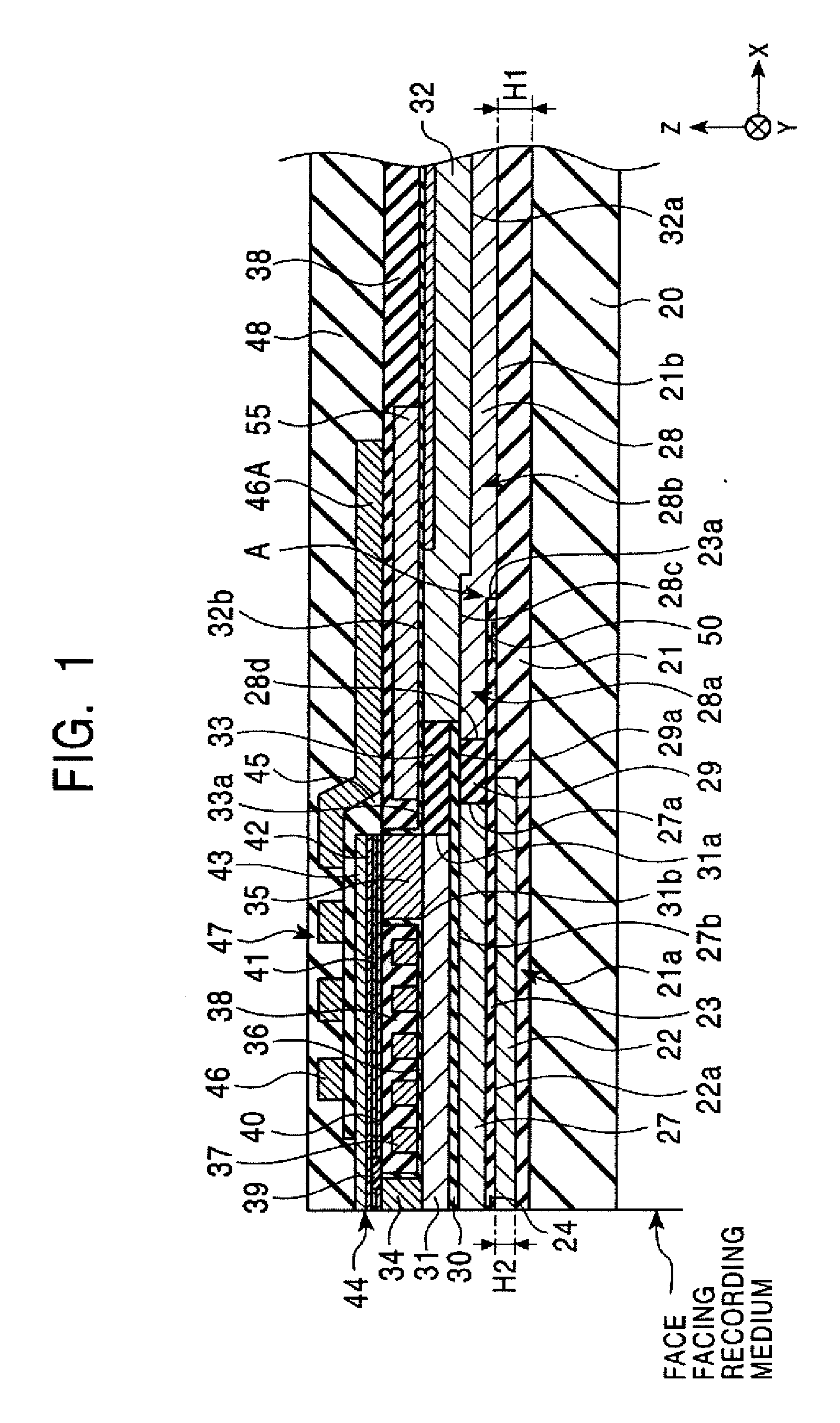
[0072]FIG. 1 is a partial longitudinal section view illustrating the structure of the thin-film magnetic head according to the present invention.

[0073] Note that in the following, the X direction in the drawing will be called the track width direction, and the Y direction in the drawing will be called the height direction. Also, the Z direction in the drawing is the direction of movement of the recording medium (magnetic disk). Also, the front edge face of the thin-film magnetic head (the face farthest to the left in FIG. 1) will be called the “face facing the recording medium”. Further, in each layer, the term “front edge face” means the left side in FIG. 1, and the term “rear edge face” means the right side in FIG. 1.

[0074] Also, the thin-film magnetic head described with reference to the drawings is a thin-film magnetic head which is a compound type thin-film magnetic head of a recording head portion (also referred to as “inductive head”) and a reproducing head portion (also ref...

fourth embodiment

[0120]FIG. 6 is a partial longitudinal section view illustrating the structure of the thin-film magnetic head according to the present invention. While only the reproducing head (MR head) is shown in FIG. 6, the structure of the recording head provided on the reproducing head portion has already been illustrated by way of FIGS. 1 through 3, any arrangement of which may be employed, and accordingly the structure of the recording head has been omitted from the drawing. FIG. 6 will be described primarily with regard to the structure near the under layer 21, which is a structural feature.

[0121] With the thin-film magnetic head shown in FIG. 6, a first recess 21a is formed in the under layer 21 formed on the slider 20, extending in the height direction form the face facing the recording medium, with the lower shield layer 22 formed within this first recess 21a.

[0122] Further, a second recess 21c extending in the height direction is formed in the under layer 21 further hindwards in the h...

fifth embodiment

[0135]FIG. 7 is a partial longitudinal section view illustrating the structure of the thin-film magnetic head according to the present invention. The point that differs from the thin-film magnetic head shown in FIG. 6 is that a third recess 21d is formed in the under layer 21 further hindwards in the height direction than the lower shield layer 22 formed embedded in the first recess 21 a formed in the under layer 21, and a hind region 28b of the second metal layer 28 formed extending in the height direction from above the gap layer 23 covering over the magnetoresistance effect element 24 and the electrode extracting layer 50 bends downwards at a step B between the gap layer 23 and the third recess 21d and is formed embedded within the third recess 21d. Embedding the hind region 28b of the second metal layer 28 in the third recess 21d enables the hind region 28b of the second metal layer 28 and the slider 20 to be brought into closer proximity. With the embodiment shown in FIG. 7, th...


PUM

PropertyMeasurementUnit
depth H2aaaaaaaaaa
depth H2aaaaaaaaaa
track width Twaaaaaaaaaa

Abstract

A lower shield layer is formed by being embedded in a first recess formed in an under layer. Accordingly, the distance between the lower shield layer and a slider can be reduced. Also, a second metal layer is formed from above a gap layer covering an electrode extracting layer over above the under layer hindwards therefrom. Accordingly, the second metal layer can be brought closer to the slider side than an upper shield layer. Consequently, the thermal dissipation effects of the thin-film magnetic head can be improved.

Description

[0001] This patent document is a divisional application and claims the benefit pursuant to 35 U.S.C. § 121 of U.S. application Ser. No. 10 / 794,753 filed on Mar. 5, 2004, which has been allowed and is hereby incorporated in its entirety by reference. This application also claims the benefit of priority to Japanese Patent Application No. 2003-060962 filed Mar. 7, 2003, herein incorporated in its entirety by reference.BACKGROUND OF THE INVENTION [0002] 1. Field of the Invention [0003] The present invention relates to a thin-film magnetic head having a magnetoresistance effect element for example, and shield layers thereabove and thereunder, and particularly relates to a thin-film magnetic head with superb thermal dissipation. [0004] 2. Description of the Related Art [0005] Thin-film magnetic heads mounted in hard disk devices and the like are generally compound type thin-film magnetic heads of reproducing MR heads which exhibit giant magnetoresistve effects and recording inductive head...

Claims


Application Information

Patent Timeline
Patent Type & Authority Applications(United States)
IPC IPC(8): G11B5/33G11B5/31G11B5/39G11B5/40
CPCB82Y10/00Y10T29/49052G11B5/3103G11B5/3106G11B5/313G11B5/3133G11B5/3136G11B5/3163G11B5/3903G11B5/40G11B2005/3996Y10T29/49043Y10T428/1171Y10T29/49046Y10T29/49048Y10T29/49073Y10T428/1143Y10T428/1193Y10T29/49034B82Y25/00Y10T428/3183
Inventor SATO, KIYOSHIGOCHOU, HIDEKIYAZAWA, HISAYUKI
Owner TDK CORPARATION
Why Eureka
Try Eureka