
Novel architecture to monitor isolation integrity between floating gate and source line

Inactive Publication Date: 2005-10-27
TAIWAN SEMICON MFG CO LTD
View PDF5 Cites 3 Cited by
  • Summary
  • Abstract
  • Description
  • Claims
  • Application Information

AI Technical Summary

Benefits of technology

[0012] A principal object of the present invention is to provide an effective and very manufacturable method to manufacture an integrated circuit device.
[0014] A yet further object of the present invention is to provide a monitoring method wherein floating gate isolation integrity is measured early in the process flow to thereby reduce the cost of scrap.
[0018] Another further object of the present invention is to provide a method to monitor floating gate isolation integrity that does not alter production wafers or production manufacturing processes.

Problems solved by technology

Once power is removed, the RAM cell discharges and the data value is lost.
However, the charge storage capability may be compromised.
The testing of nonvolatile memory arrays presents a unique testing problem because each cell in the array will need to be erased, programmed, and then read in each possible state (0 and 1).
The complete manufacturing process flow is therefore expensive and time consuming.
However, if a larger problem occurs such that redundancy is not sufficient to fix the problem, then the circuits are scrapped.
A wafer-wide problem may cause the entire wafer to be scrapped and thereby result in a loss of the entire processing investment.
It is found that a significant cause for such scrap is the integrity or quality of the dielectric isolation surrounding the floating gates.

Method used


Image

  • Novel architecture to monitor isolation integrity between floating gate and source line
  • Novel architecture to monitor isolation integrity between floating gate and source line
  • Novel architecture to monitor isolation integrity between floating gate and source line

Examples


Embodiment Construction

[0027] The preferred embodiments of the present invention disclose a method to manufacture an integrated circuit device. A novel testing structure is disclosed for monitoring floating gate isolation integrity in a flash EEPROM process. A novel method to use the testing structure is disclosed. It should be clear to those experienced in the art that the present invention can be applied and extended without deviating from the scope of the present invention.

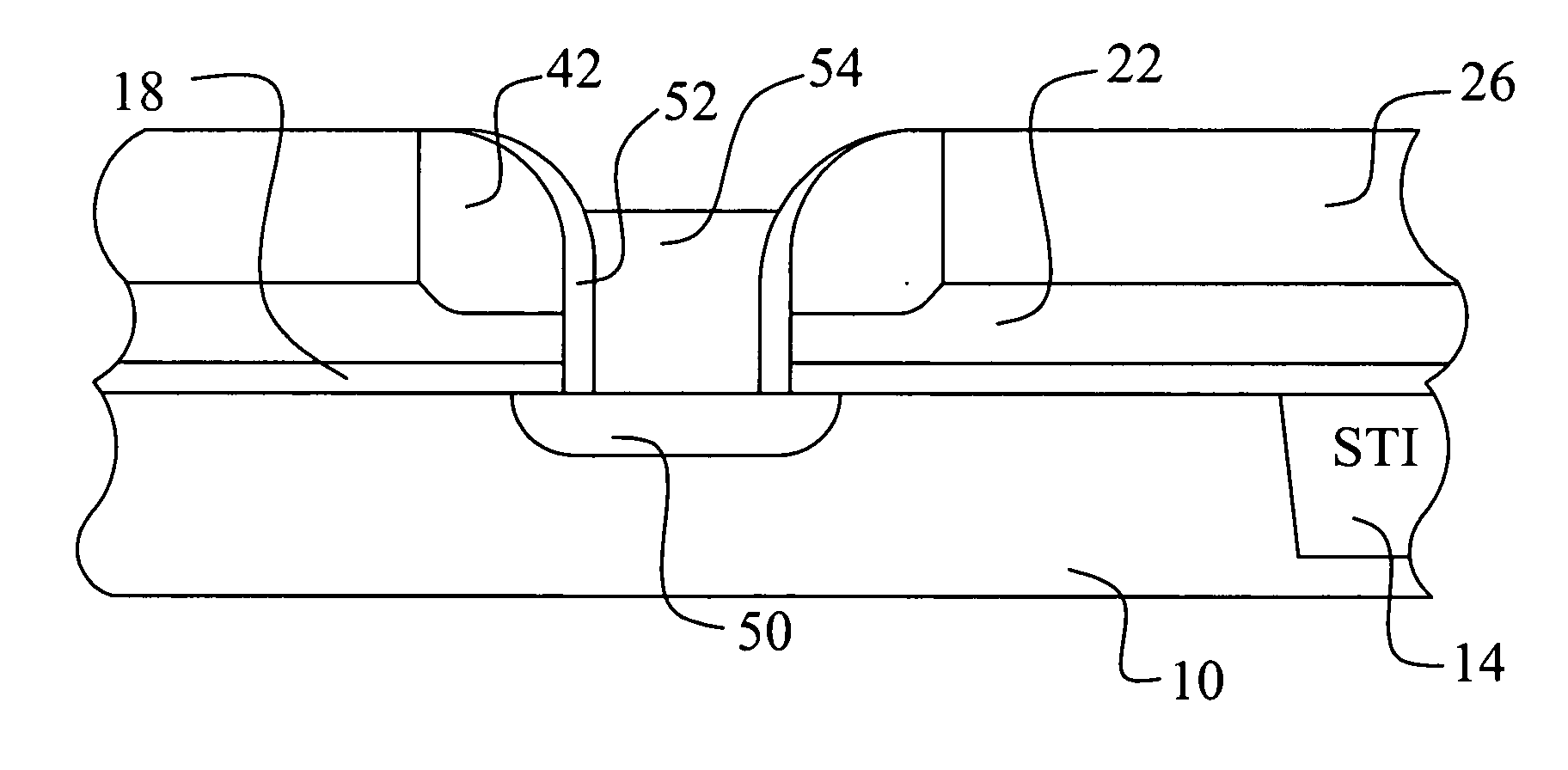
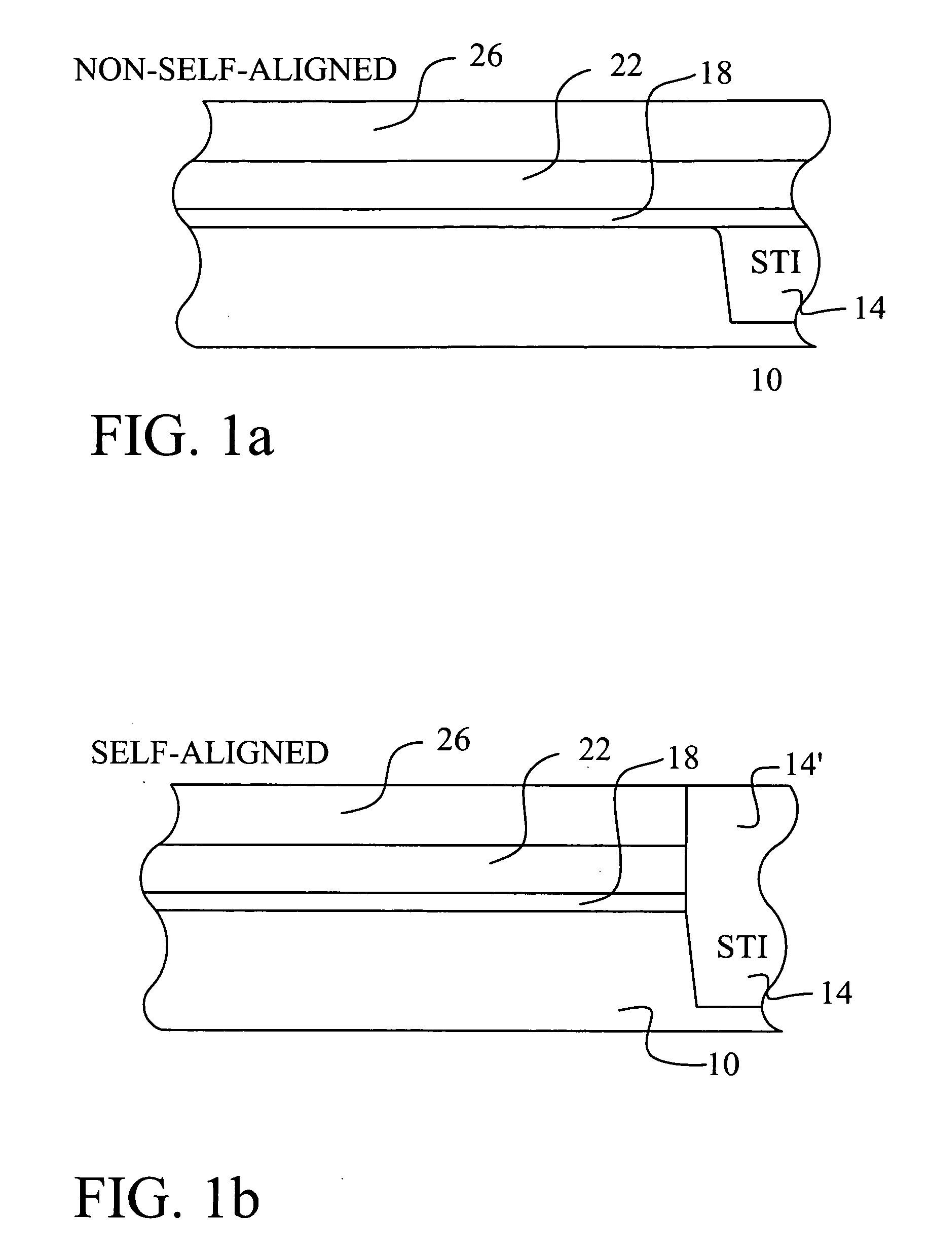
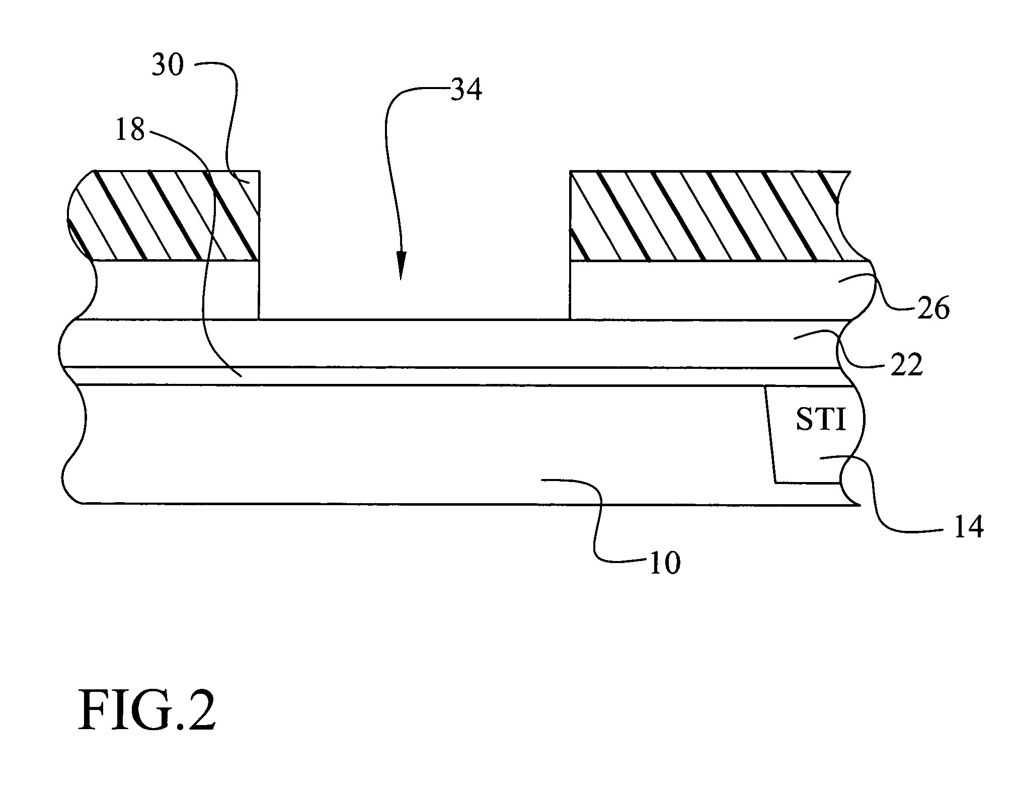
[0028] Referring now to FIGS. 1 through 11, a first embodiment of the present invention is illustrated. The embodiment shows a method to form a test structure for evaluating floating gate isolation in a memory device. Several important features of the present invention are shown and discussed below. The test structure is formed on an integrated circuit wafer. Preferably, the wafer is a monitoring wafer that is included as part of a production lot of wafers. For example, a production lot of 24 wafers might include a monitoring wafer....


PUM


Abstract

A new method to form a floating gate isolation test structure in the manufacture of a memory device is achieved. The method comprises providing a substrate. A gate oxide layer is formed overlying the substrate. A floating gate conductor layer is deposited overlying the gate oxide layer. The floating gate conductor layer is patterned to expose the substrate for planned source regions. Ions are implanted into the exposed substrate to form the source regions. Contacting structures are formed to the source regions. Contacting structures are formed to the floating gate conductor layer.

Description

BACKGROUND OF THE INVENTION [0001] (1) Field of the Invention [0002] The invention relates to integrated circuit devices, and more particularly, to a method to monitor isolation integrity of the floating gate in the manufacture of a nonvolatile memory device. [0003] (2) Description of the Prior Art [0004] Memory devices are an important building block in the art of integrated circuit design and manufacture. Memory devices are used for temporary and permanent data storage in the integrated circuit or system. For example, a random access memory, or RAM, can be used to temporarily store data values. RAM memories are formed in static or dynamic forms. In either case, RAM requires a continuous power supply in order to retain the data. Once power is removed, the RAM cell discharges and the data value is lost. In read-only memory, or ROM, data is permanently stored. Removal of the power supply doesn't erase the data state. Nonvolatile programmable memory devices, such as electrically erasa...

Claims


Application Information

Patent Timeline
IPC IPC(8): H01L21/28H01L21/336H01L21/8247H01L23/544H01L27/115
CPCH01L21/28273H01L22/34H01L27/115H01L27/11521H01L2924/0002H01L2924/00H01L29/40114H10B69/00H10B41/30
Inventor HSIEH, CHANG-JENSUNG, HUNG-CHENGHSU, TE-HSUN
Owner TAIWAN SEMICON MFG CO LTD
Learn More