Self-alignment magnetic connector reduced in size

Inactive Publication Date: 2005-10-27
JAPAN AVIATION ELECTRONICS IND LTD
View PDF1 Cites 88 Cited by
  • Summary
  • Abstract
  • Description
  • Claims
  • Application Information

AI Technical Summary

Benefits of technology

[0005] It is therefore an object of the present invention to provide a magnetic c

Problems solved by technology

However, the above-mentioned structure including the guide ramps results in an increase in size of the connector.
Therefore, the above-mentioned technique is not suitable for a rece

Method used


Image

  • Self-alignment magnetic connector reduced in size
  • Self-alignment magnetic connector reduced in size
  • Self-alignment magnetic connector reduced in size

Examples


first embodiment

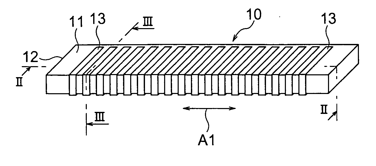
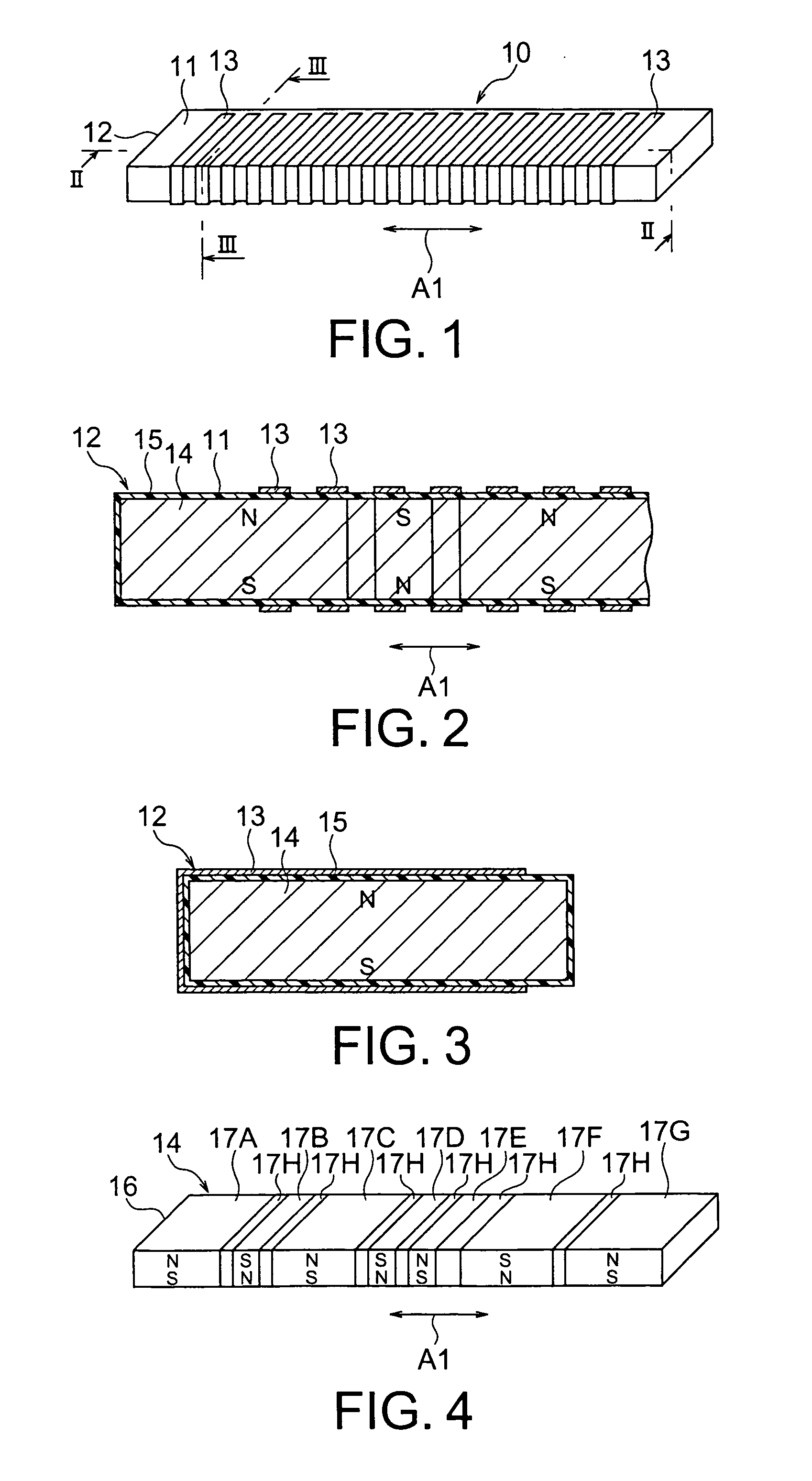
[0034] At first referring to FIGS. 1 to 3, description will be made of a magnetic connector according to this invention.

[0035] The magnetic connector 10 illustrated in the figures acquires connection with a mating connector (not shown) by magnetic attractive force. The magnetic connector 10 comprises a base member 12 having a particular surface 11 as a flat surface to be faced to the mating connector upon acquiring connection, and a plurality of conductive electrode terminals 13 fixed to the base member 12 at a predetermined pitch to be electrically connected to the mating connector. The base member 12 has a magnetic force generating portion 14 for generating magnetic force, and an elastic insulating layer 15 connected to the magnetic force generating portion 14 and defining the particular surface 11. The magnetic force generating portion 14 has different magnetic poles, i.e., N and S poles, alternately arranged along the particular surface 11 in a predetermined direction A1.

[0036]...

second embodiment

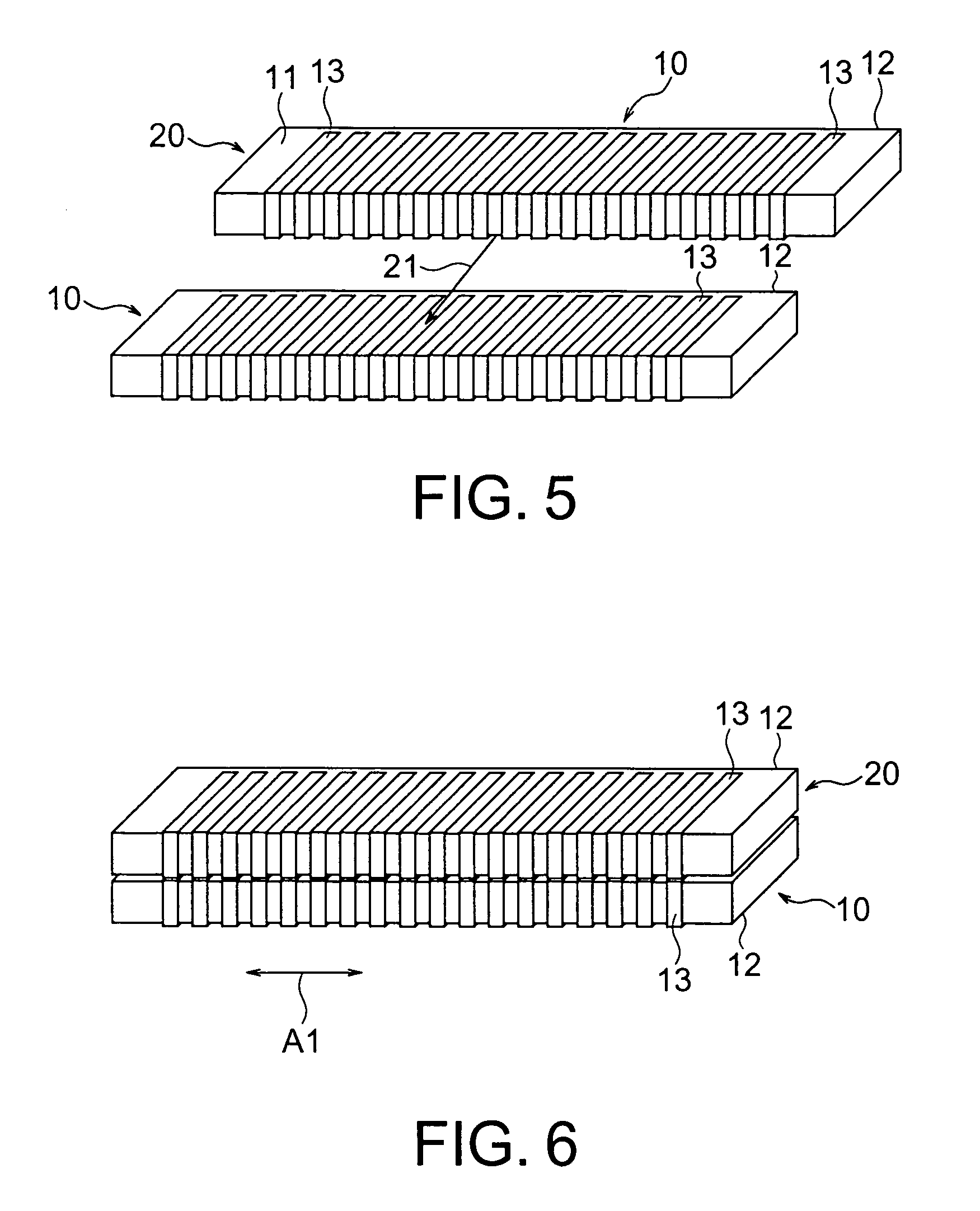
[0045] Referring to FIGS. 7 through 9, a magnetic connector according to this invention will be described. Similar parts are designated by like reference numerals and description thereof will be omitted.

[0046] In each of the connector 10 and the mating connector 20 illustrated in the figures, the N and the S poles of the magnetic force generating portion 14 are formed by a plurality of, i.e., four permanent magnets 17A to 17D which are different in size and arranged in series in tight contact with one another. The insulating layer 15 depicted by dotted lines comprises an elastic material such as gel, elastomer, or polyamide fiber. In FIGS. 8 and 9, an N pole side of each magnet is hatched so as to distinguish the polarity.

[0047] One of the two magnetic force generating portions 14 illustrated in FIG. 8 is used in the connector 10 while the other is used in the mating connector 20. The permanent magnets 17A to 17D of these magnetic force generating portions 14 are designed to be rev...

third embodiment

[0048] Referring to FIG. 10, description will be made of a magnetic connector according to this invention. Similar parts are designated by like reference numerals and description thereof will be omitted.

[0049] The connector illustrated in the figure includes a cohesive layer or a first layer 22 between the magnetic force generating portion 14 and the electrode terminals 13 as thin film electrodes. The permanent magnets 17A to 17D are adhered to a lower surface of the first layer 22. The electrode terminals 13 are adhered to the particular surface 11 defined by an upper surface of the cohesive layer 22. As the first layer 22, gel is used. The magnetic force generating portion 14 has a lower surface with the insulating layer 15 formed thereon.


PUM


Abstract

In a magnetic connector acquiring connection with a mating connector by magnetic force, a base member has a particular surface to be faced to the mating connector upon connection. An electrode terminal is fixed to the base member and adapted to be electrically connected to the mating connector. The base member has a magnetic force generating portion having a plurality of magnetic poles for producing the magnetic force. N and the S poles of the magnetic poles are alternately arranged along the particular surface in a predetermined direction. Thus, the connector is properly positioned relative to the mating connector by the magnetic force.

Description

BACKGROUND OF THE INVENTION [0001] This invention relates to a connector acquiring connection by magnetic force (herein referred to as a “magnetic connector”). [0002] A connector of the type is disclosed, for example, in Japanese Patent Application Publication (JP-A) No. H6-342679 and comprises a body provided with a pin contact and a magnet. By attractive force of the magnet, a mating connector is attracted so that the pin contact is contacted with a contact member of the mating connector. Thus, electrical connection between the connector and the mating connector is obtained. [0003] In order to avoid misalignment or displacement between the pin contact and the contact member of the mating connector, the body is provided with a pair of guide ramps or slopes. Upon connection, the mating connector is guided between the guide ramps and automatically adjusted in relative position with respect to the connector. Thus, reliable contact between the pin contact and the contact member of the ...

Claims


Application Information

Patent Timeline
IPC IPC(8): H01R11/30H01R13/62
CPCH01R11/30H01R13/6205H05K2201/083H05K2201/058H05K3/365
Inventor TAI, TOMISHIGEAKIMOTO, HIROSHIARAI, KATSUMIUCHIDATE, TAKAHIROKOGUCHI, MITSUO
Owner JAPAN AVIATION ELECTRONICS IND LTD
Why Eureka
Try Eureka