ROM-based controller monitor in a memory device

Active Publication Date: 2005-10-27
MICRON TECH INC
View PDF16 Cites 2 Cited by
  • Summary
  • Abstract
  • Description
  • Claims
  • Application Information

AI Technical Summary

Problems solved by technology

However, it is very difficult to determine which step the algorithm controller is executing at any particular time.
However, the internal probing cannot detect more than a few signals at the same time and cannot be performed on integrated circuits that are encapsulated in a package.

Method used


Image

  • ROM-based controller monitor in a memory device
  • ROM-based controller monitor in a memory device
  • ROM-based controller monitor in a memory device

Examples


Embodiment Construction

[0019] In the following detailed description of the invention, reference is made to the accompanying drawings that form a part hereof, and in which is shown, by way of illustration, specific embodiments in which the invention may be practiced. In the drawings, like numerals describe substantially similar components throughout the several views. These embodiments are described in sufficient detail to enable those skilled in the art to practice the invention. Other embodiments may be utilized and structural, logical, and electrical changes may be made without departing from the scope of the present invention. The following detailed description is, therefore, not to be taken in a limiting sense, and the scope of the present invention is defined only by the appended claims and equivalents thereof.

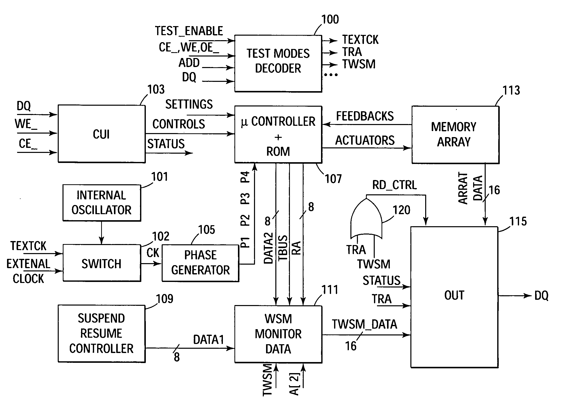
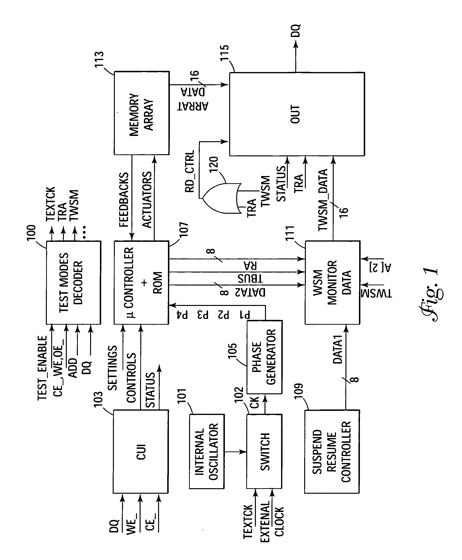
[0020]FIG. 1 illustrates a block diagram of one embodiment of the monitor circuit of the present invention. The monitor circuit, used for test / debug purposes, tracks the activity of a flash me...


PUM


Abstract

A circuit to monitor the activity of a memory device during program / erase operations that are managed by a ROM-based microcontroller. Different signals can be monitored according to different test modes. The ROM-based microcontroller is triggered by a clock that can be connected to an internal fixed frequency oscillator or to an external clock source for which the frequency can be varied from 0 Hz to any frequency required by the application. The circuit outputs state machine status data, read only memory addresses, and memory status information in a series of multiplexing operations to provide a tester with the ability to determine the state of a memory device during various memory operations.

Description

RELATED APPLICATION [0001] This application is a divisional application of U.S. patent application Ser. No. 10 / 696,973 (pending) filed Oct. 30, 2003 and titled, ROM-BASED CONTROLLER MONITOR IN A MEMORY DEVICE, which claims priority to Italian Patent Application Serial No. RM2003A000198, filed Apr. 28, 2003, entitled “ROM-BASED CONTROLLER MONITOR IN A MEMORY DEVICE,” which is commonly assigned.TECHNICAL FIELD OF THE INVENTION [0002] The present invention relates generally to memory devices and in particular the present invention relates to testing and / or debugging flash memory devices. BACKGROUND OF THE INVENTION [0003] Flash memory devices have developed into a popular source of non-volatile memory for a wide range of electronic applications. Flash memory devices typically use a one-transistor memory cell that allows for high memory densities, high reliability, and low power consumption. Common uses for flash memory include portable computers, personal digital assistants (PDAs), dig...

Claims


Application Information

Patent Timeline
IPC IPC(8): G01R31/28G06F9/00G06F9/24G06F11/00G06F15/177G11C7/00G11C17/00G11C29/16G11C29/48
CPCG11C16/04G11C29/12015G11C29/50004G11C29/48G11C29/16
Inventor NASO, GIOVANNIPISTILLI, PASQUALEDE SANTIS, LUCACONENNA, PASQUALE
Owner MICRON TECH INC
Why Eureka
Try Eureka