System and method enabling configuration of physical layer devices and corresponding link partners for communicating network data via a configuration source or auto-negotiation

a physical layer device and configuration source technology, applied in the field of local area network interface for a multiple port device, can solve the problem that the chip number has no direct method of determining the results of autonegotiation

Inactive Publication Date: 2005-02-22
ADVANCED MICRO DEVICES INC
View PDF8 Cites 83 Cited by
  • Summary
  • Abstract
  • Description
  • Claims
  • Application Information

AI Technical Summary

Problems solved by technology

However, if a PHY transceiver is configured via autonegotiation, only the NID that was involved in the autonegotiation kn

Method used


Image

  • System and method enabling configuration of physical layer devices and corresponding link partners for communicating network data via a configuration source or auto-negotiation
  • System and method enabling configuration of physical layer devices and corresponding link partners for communicating network data via a configuration source or auto-negotiation
  • System and method enabling configuration of physical layer devices and corresponding link partners for communicating network data via a configuration source or auto-negotiation

Examples


Embodiment Construction

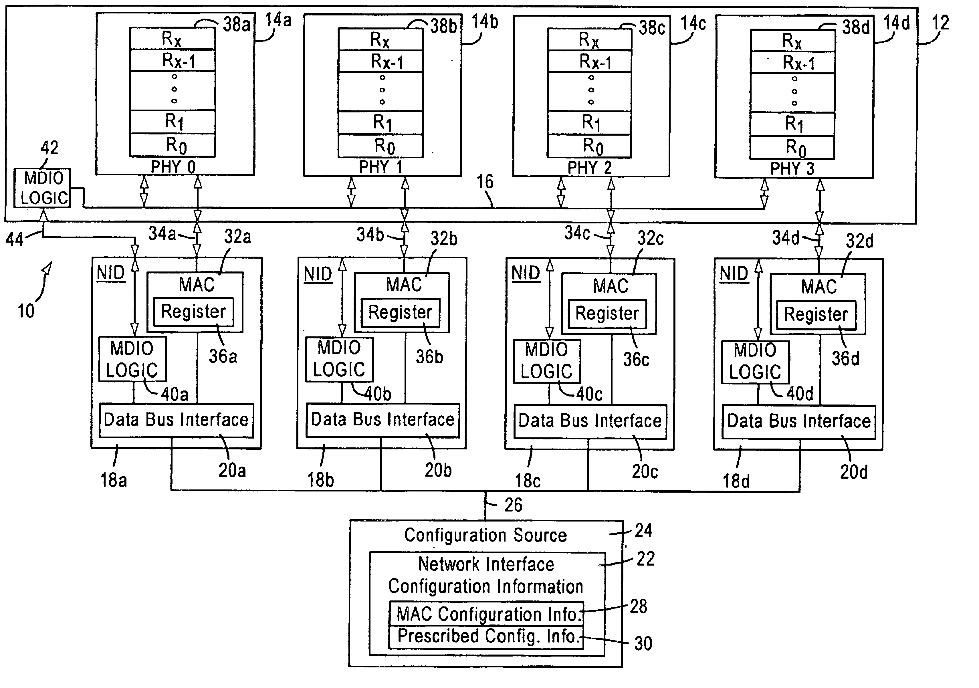
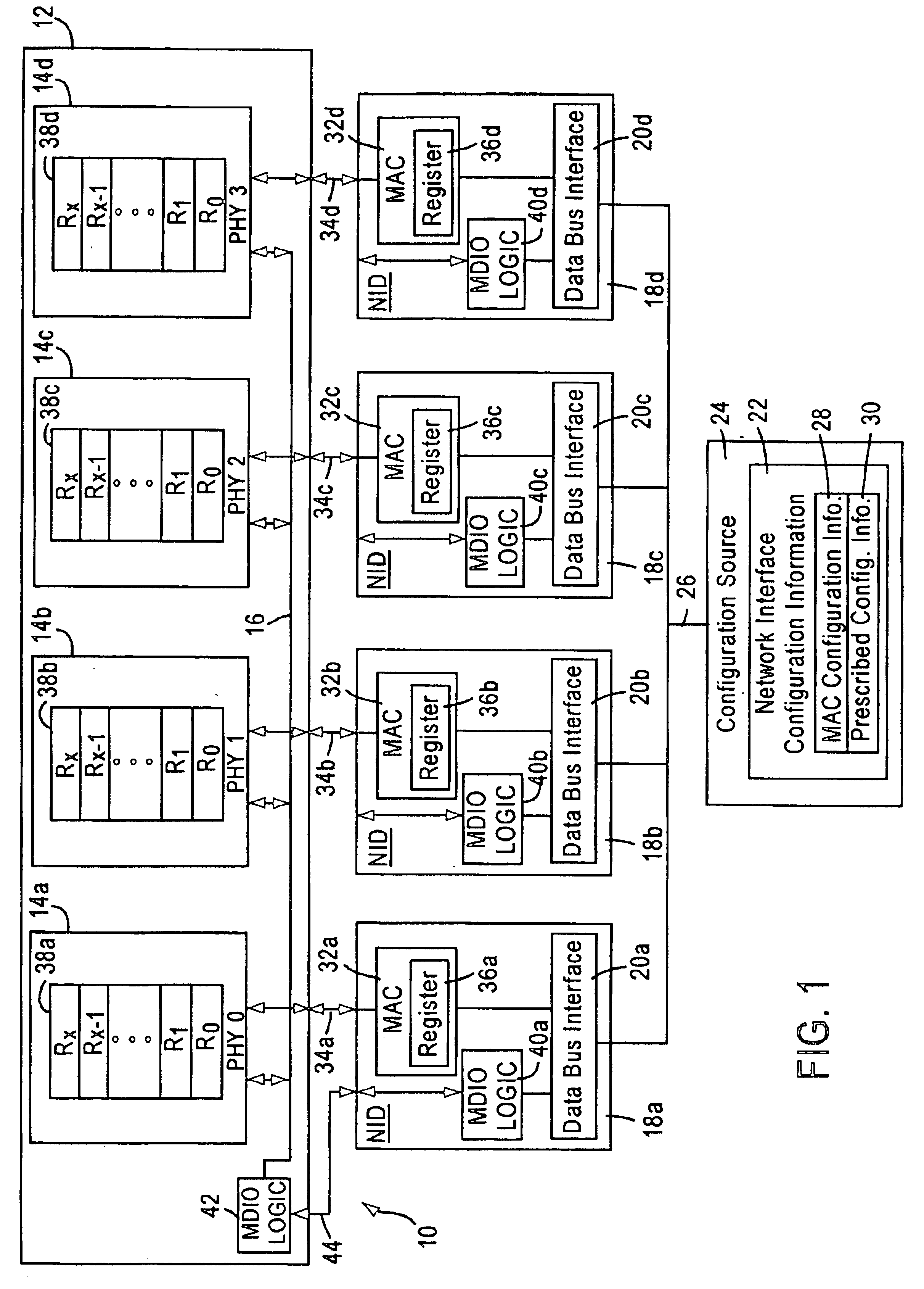
FIG. 1 is a block diagram of an exemplary network interface 10 in an Ethernet (ANSI / IEEE 802.3) network where the network interface 10 includes a plurality of physical layer devices (PHYs) 14a, 14b, 14c, and 14d. Each of the PHYs 14a, 14b, 14c, and 14d is configured for communicating network data to a link partner (not shown) according to one of an autonegotiation protocol or prescribed configuration information 30 from a shared management data bus 16. A plurality of network interface devices (NIDs) 18a, 18b, 18c, and 18d, each having a data bus interface 20a, 20b, 20c, and 20d, respectively, receive network interface configuration information 22 from a configuration source 24 via a data bus 26. The network interface configuration information 22 comprises media access controller (MAC) configuration information 28 and the prescribed configuration information 30. In addition to the data bus interface 20a, 20b, 20c, and 20d, each NID 18a, 18b, 18c, and 18d includes a media access contr...


PUM


Abstract

A network interface configures a plurality of physical layer devices and a corresponding plurality of network interface devices to allow for the communication of network data between the physical layer devices and corresponding link partners. At least one of the network interface devices is configured as a master device that communicates management information and autonegotiation results with the physical layer devices, while the other network interface devices do not. A configuration source, such as a central processing unit (CPU) or electronic erasable programmable read only memory (EEPROM), receives the autonegotiation results from the physical layer devices, through the master device, and configures the media access controllers (MACs) of each of the network interface devices in accordance with the autonegotiation results. This forces the MACs into their respective proper configurations even though the network interface devices that are not master devices do not receive the autonegotiation results directly from their corresponding physical layer devices.

Description

FIELD OF THE INVENTIONThe present invention relates to a local area network interface for a multiple port device, more particularly to an arrangement for configuring physical layer devices of the multiple port devices in order to communicate network data between each physical layer device and corresponding link partners.BACKGROUND ARTLocal area networks use a network cable or other network media to link nodes (e.g., workstations, routers and switches) to the network. Each local area network architecture uses a media access control (MAC) enabling network interface device (NID) at each network node to share access to the media.Traditional Ethernet networks (10BASE-T) operate at 10 Mb / s Ethernet protocol, as described by IEEE Standard 802.3; the majority of Ethernet interfaces currently operate at this data rate. However, a newer Ethernet standard, under IEEE standard 802.3 u, accomplishes the faster operation of 100 BASE-T systems, at a 100 Mb / s data rate (i.e., a 125 Mb / s encoded bit...

Claims


Application Information

Patent Timeline
IPC IPC(8): H04L29/06H04L12/24
CPCH04L29/06H04L41/0806H04L69/24H04L9/40
Inventor WILLIAMS, ROBERT
Owner ADVANCED MICRO DEVICES INC
Why Eureka
Try Eureka