
Decoding device, decoding method, and program

a decoding device and decoding method technology, applied in the field of decoding apparatus, decoding method, program, can solve the problems of large difficulty in analysis difficult for decoding apparatus of figs, etc., and achieve the effect of suppressing operating frequency and easily controlling memory access

Active Publication Date: 2005-10-27
SONY CORP
View PDF11 Cites 38 Cited by
  • Summary
  • Abstract
  • Description
  • Claims
  • Application Information

AI Technical Summary

Benefits of technology

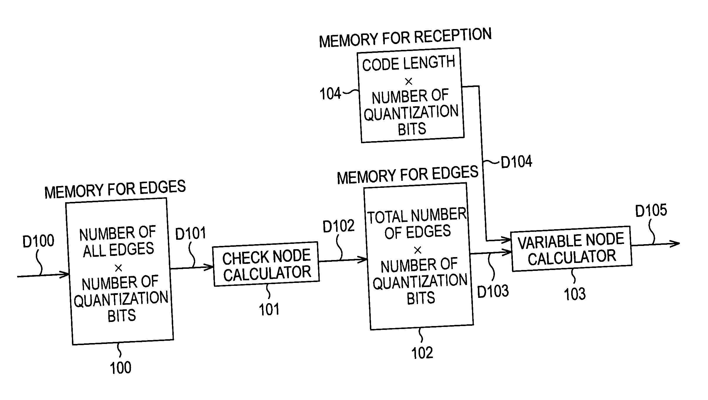
[0109] The present invention has been made in view of such circumstances. An object of the present invention is to suppress the operating frequency to a sufficiently realizable range while suppressing the circuit scale for both logic and memory, and to be capable of easily controlling memory access.

Problems solved by technology

This necessitates analysis involving a large degree of difficulty.
When the decoding apparatus of FIGS. 12A to 12C is configured as an apparatus for performing the decoding of LDPC codes having a particular check matrix, of a particular code length and a particular coding rate, it is difficult for the decoding apparatus to perform the decoding of LDPC codes having another check matrix, of another code length and another coding rate.
That is, unlike the decoding apparatus of FIG. 9, it is difficult for the decoding apparatus of FIGS. 12A to 12C to deal with the decoding of various codes even if the control signal is changed only, and the dependence on codes is high.
In this case, there are problems in that, generally, it is not easy to avoid simultaneous read-out from or simultaneous writing to different addresses of the memory, and memory access control is difficult.
However, in this method, the deterioration of performance is caused to occur.
However, in the method in which computations of messages corresponding to the edges are performed one-by-one, a high operating frequency is required.
In the method in which the computations of messages are performed in units of several computations in parallel, control of memory access is difficult.

Method used


Image

  • Decoding device, decoding method, and program
  • Decoding device, decoding method, and program
  • Decoding device, decoding method, and program

Examples


Embodiment Construction

[0190] Specific embodiments to which the present invention is applied will be described below in detail with reference to the drawings.

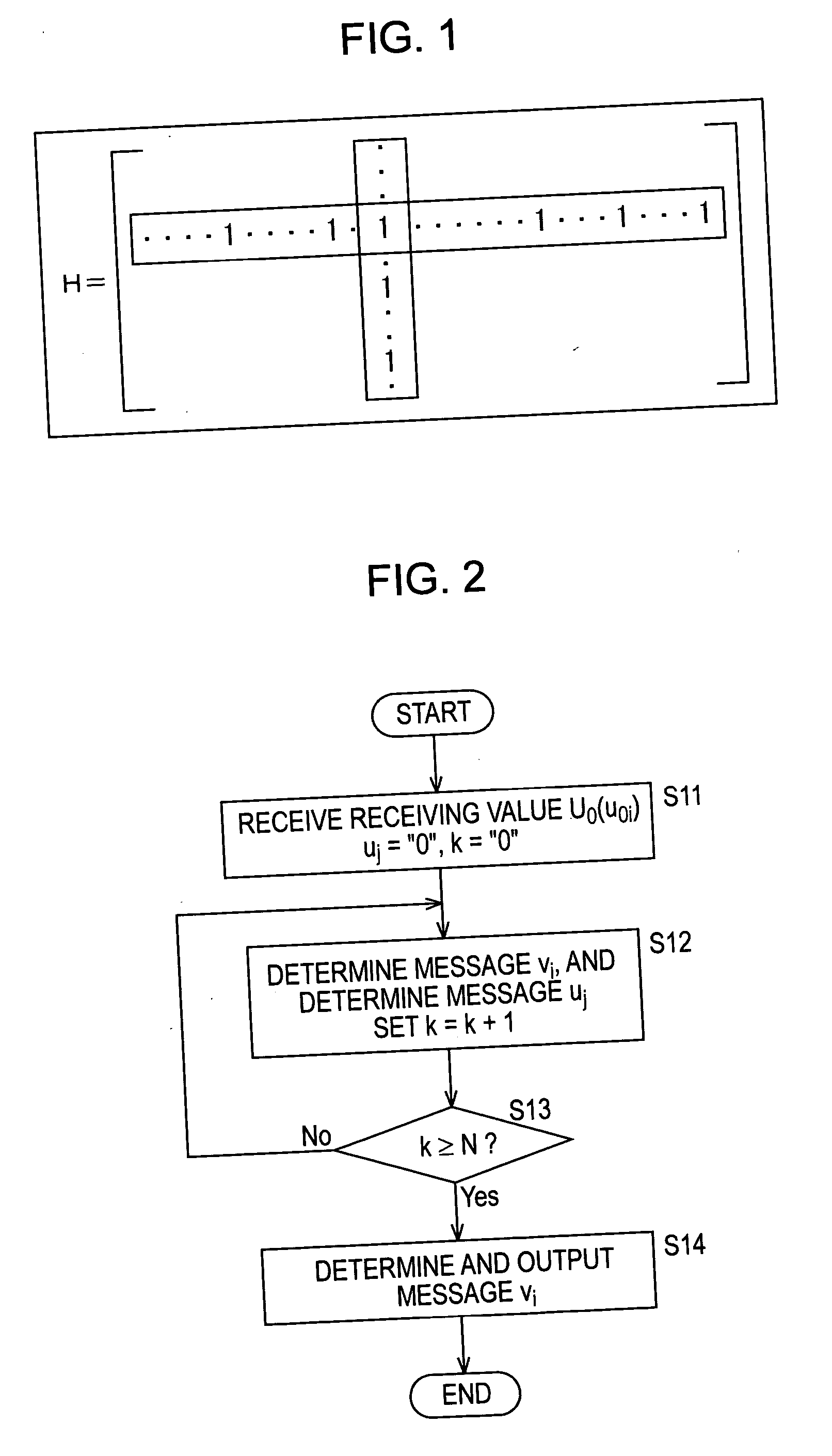
[0191]FIG. 15 shows an example of a 30×9 check matrix, which are divided in units of 5×5 matrices. The check matrix of FIG. 15 is the same as the check matrix shown in FIG. 8.

[0192] In FIG. 15, the check matrix is represented by a combination of a 5×5 unit matrix, a matrix in which one or more is, which are elements of the unit matrix, are substituted with 0 (hereinafter referred to as a “quasi-unit matrix” where appropriate), a matrix in which the unit matrix or the quasi-unit matrix is cyclically shifted (hereinafter referred to as a “shift matrix” where appropriate), a sum of two or more (plural) of the unit matrix, the quasi-unit matrix, and the shift matrix (hereinafter referred to as a “sum matrix” where appropriate), and a 5×5 0-matrix. The LDPC codes represented by the check matrix of FIG. 15 have a coding rate of ⅔ and a code length of 9. ...


PUM


Abstract

The present invention relates to a decoding apparatus and a decoding method for realizing the decoding of LDPC codes, in which, while the circuit scale is suppressed, the operating frequency can be suppressed within a sufficiently feasible range, and control of memory access can be performed easily, and to a program therefor. A check matrix of LDPC codes is formed by a combination of a (P×P) unit matrix, a matrix in which one to several 1s of the unit matrix are substituted with 0, a matrix in which they are cyclically shifted, a matrix, which is the sum of two or more of them, and a (P×P) 0-matrix. A check node calculator 313 simultaneously performs p check node calculations. A variable node calculator 319 simultaneously performs p variable node calculations.

Description

TECHNICAL FIELD [0001] The present invention relates to a decoding apparatus, a decoding method, and a program. More particularly, the present invention relates to a decoding apparatus and a decoding method for decoding codes on which coding is performed using low density parity check codes (LDPC codes), and to a program therefor. BACKGROUND ART [0002] In recent years, research in, for example, communication fields such as mobile communication and deep space communication, and broadcasting fields such as terrestrial-wave or satellite digital broadcasts has progressed remarkably. Along with this situation, research on coding theories for making error correction coding and decoding efficient has been actively carried out. [0003] As a theoretical limit of code performance, the Shannon limit implied by the so-called Shannon's (C. E. Shannon) channel coding theorem is known. Research on coding theories has been carried out for the purpose of developing codes exhibiting performance near t...

Claims


Application Information

Patent Timeline
IPC IPC(8): H03M13/11G06F11/10H03M13/19
CPCH03M13/11H03M13/1114H03M13/1137H03M13/1168H03M13/1145H03M13/6505H03M13/6566H03M13/6577H03M13/1134H03M13/1188H03M13/09H03M13/19
Inventor YOKOKAWA, TAKASHIMIYAUCHI, TOSHIYUKIIIIDA, YASUHIRO
Owner SONY CORP
Learn More