Self-stabilizing, floating microelectromechanical device

a microelectromechanical and self-stabilizing technology, applied in the direction of generators/motors, snap-action arrangements, instruments, etc., can solve the problems that devices typically require complex means to control and stabilize the position of proof mass, and achieve the effects of reducing or eliminating mechanical parasitic effects, reducing the danger of short circuits, and substantially eliminating mechanical wear

Inactive Publication Date: 2005-11-03
RGT UNIV OF CALIFORNIA
View PDF16 Cites 34 Cited by
  • Summary
  • Abstract
  • Description
  • Claims
  • Application Information

AI Technical Summary

Benefits of technology

[0012] The present invention relates to a floating MEMS device (FLEMS) in which a proof mass is levitated electrostatically without the need for feedback control means and, once levitated, without mechanical contact between the proof mass and any other portion of the device. This is in contrast with other MEMS devices, including accelerometers and inertial sensors, in which deflection of a mechanically-coupled proof mass, cantilevered beam or other structure is the basis for measuring acceleration. In various embodiments of the present non-contact floating MEMS device, mechanical wear is substantially eliminated and mechanical parasitic effects are sharply reduced or eliminated. Thus, an important objective of the present invention is to produce a floating MEMS device in which the proof mass has no mechanical contact with other portions of the device.
[0013] Configurations of electrodes for a FLEMS device are described that, when charged with like charges as the proof mass, result in self-stabilized floating of the proof mass based upon electrostatic repulsion. Self-stabilization results from a FLEMS structure such that, when the proof mass is displaced from its equilibrium position, electrostatic forces arise tending to restore the proof to its equilibrium position. The magnitude of the restoring electrostatic forces tend to increase in magnitude as the proof mass undergoes a larger displacement from its equilibrium position. Thus, another objective of the present invention is to produce a self-stabilizing FLEMS device that does not require feedback control systems. In addition, since only like electrical charges are in close proximity, the dangers of short circuits are markedly reduced.
[0014] Perturbations causing displacement of the proof mass can conveniently be measured by measuring the changes in electrical properties of the stabilization electrodes or electrical properties of the electrodes causing floating, and / or the electrical properties of additional sensing electrodes that can be included to further enhance sensing capabilities. Drive electrodes can also be included that allow forces to be applied to the charged proof mass resulting in a floating, electrically controllable MEMS device. Numerous applications are possible including: 1) Charge storage device. 2) GHz resonator. 3) Accelerometer. 4) Wide-angle scanner. 5) Magnetometer. 6) Nanogravity sensor. 7) Inertial navigation. 8) Magnetic confinement. 9) Quantum gyros. 10) Harsh-environment applications. 11) Thermal isolation applications. 12) Micro transport.

Problems solved by technology

However, these devices typically require complex means to control and stabilize the position of the proof mass.

Method used


Image

  • Self-stabilizing, floating microelectromechanical device
  • Self-stabilizing, floating microelectromechanical device
  • Self-stabilizing, floating microelectromechanical device

Examples


examples

1. Accelerometer—Inertial Sensor

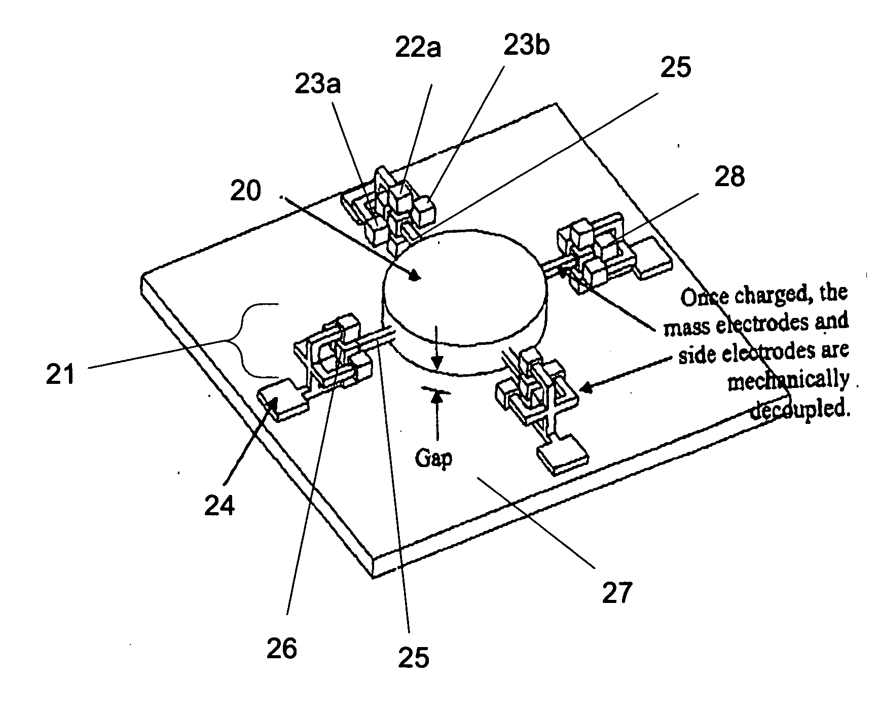
[0068] Accelerometers and inertial sensors have numerous uses including guidance and navigation, gravitational field detection, collision sensors (as for vehicle air bag deployment), among other applications. The FLEMS embodiments depicted in FIGS. 2a and 2b are useful for this application. As proof mass 20 experiences a force such as that caused by an acceleration, impact, gravitational field, among others, the charges residing on or near termination blocks 28 and side conductors 25 will undergo a displacement with respect to charges residing on the stabilizing structures 21. This charge displacement will induce voltages and / or currents that can be measured and thereby determine the displacement of proof mass 20. The displacement of proof mass 20 provides information concerning the acceleration or other environmental perturbation causing the displacement.

[0069] As depicted in FIGS. 2a and 2b, there are four termination blocks 26, each of which is ...


PUM


Abstract

The present invention relates to MicroElectroMechanical Systems (MEMS), devices and applications thereof in which a proof mass is caused to levitate by electrostatic repulsion. Configurations of electrodes are described that result in self-stabilized floating of the proof mass. The electrical properties of the electrodes causing floating, such as currents and/or voltages, typically change in response to environmental perturbations affecting the proof mass. Measuring such currents and/or voltages allow immediate and accurate measurements to be performed related to those perturbations affecting the location and/or the orientation of the proof mass. Additional sensing electrodes can be included to further enhance sensing capabilities. Drive electrodes can also be included that allow forces to be applied to the charged proof mass resulting in a floating, electrically controllable MEMS device. Several applications are described including accelerometers, inertial sensors, resonators and filters for communication devices, gyros, one and two axis mirrors and scanners, among other devices. Several fabrication methods are also described.

Description

CROSS REFERENCE TO RELATED APPLICATIONS [0001] (none). STATEMENT REGARDING FEDERALLY SPONSORED RESEARCH OR DEVELOPMENT [0002] (none). BACKGROUND OF THE INVENTION [0003] 1. Field of Invention [0004] This invention relates generally to the field of microelectromechanical (MEMS) devices and, in particular, to floating MEMS devices in which a proof mass is electrostatically levitated. [0005] 2. Description of the Prior Art [0006] Microelectromechanical (MEMS) devices are finding ever-increasing areas of application in the modern economy as trends towards miniaturization, portability, lightweight, low power consumption and low cost drive many technologies. Sensors, actuators and many other devices are all affected by the wider application of microtechnology and MEMS fabrication techniques. [0007] The present invention relates to a floating MEMS device (FLEMS) in which a proof mass is levitated electrostatically as part of a MEMS device, without the need for feedback control means and, on...

Claims


Application Information

Patent Timeline
Patent Type & Authority Applications(United States)
IPC IPC(8): B81B5/00G01P15/00G01P15/125G01P15/18G02B26/00G02B26/08
CPCB81B5/00B81B2201/0235G02B26/0841G01P15/18G02B26/001G01P15/125
Inventor CLARK, JASON VAUGHN
Owner RGT UNIV OF CALIFORNIA
Why Eureka
Try Eureka