Valve device

a valve device and valve body technology, applied in the direction of shock absorbers, water supply installations, machines/engines, etc., can solve the problems of unfavorable soot accumulation, damage to the combustion engine or damage,

Inactive Publication Date: 2005-11-03
STT EMTEC AB
View PDF10 Cites 84 Cited by
  • Summary
  • Abstract
  • Description
  • Claims
  • Application Information

AI Technical Summary

Benefits of technology

[0003] The object of the present invention is to achieve a further development of the above-

Problems solved by technology

Hereby, undesirably high exhaust gas contents in the inlet air to the combustion engine is prevented, which otherwise might cause undesired deposit of soot in the combustion e

Method used


Image

  • Valve device
  • Valve device
  • Valve device

Examples


first embodiment

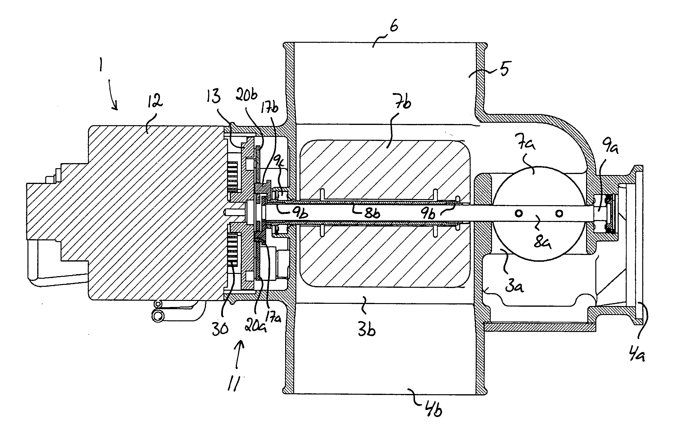
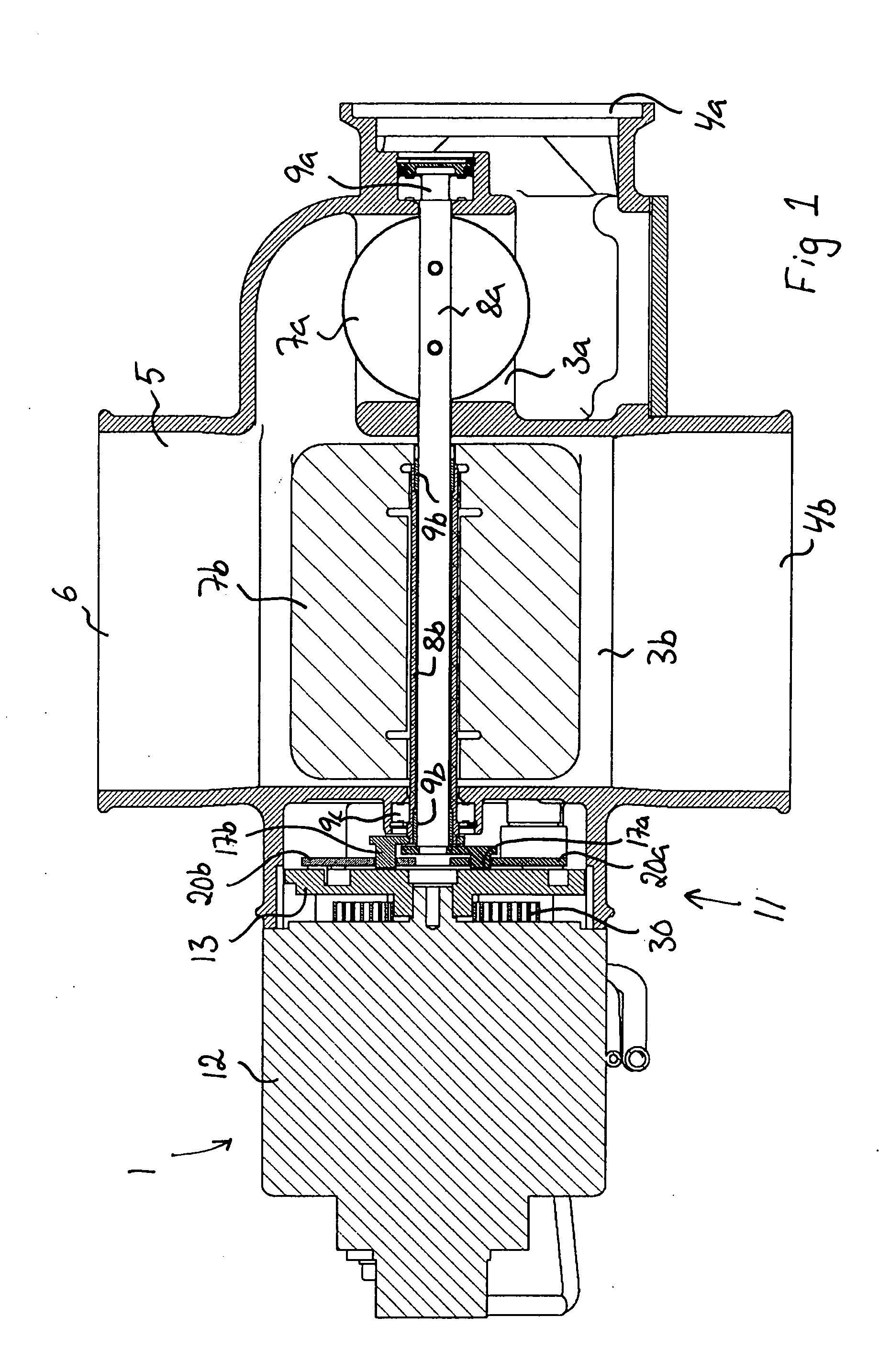
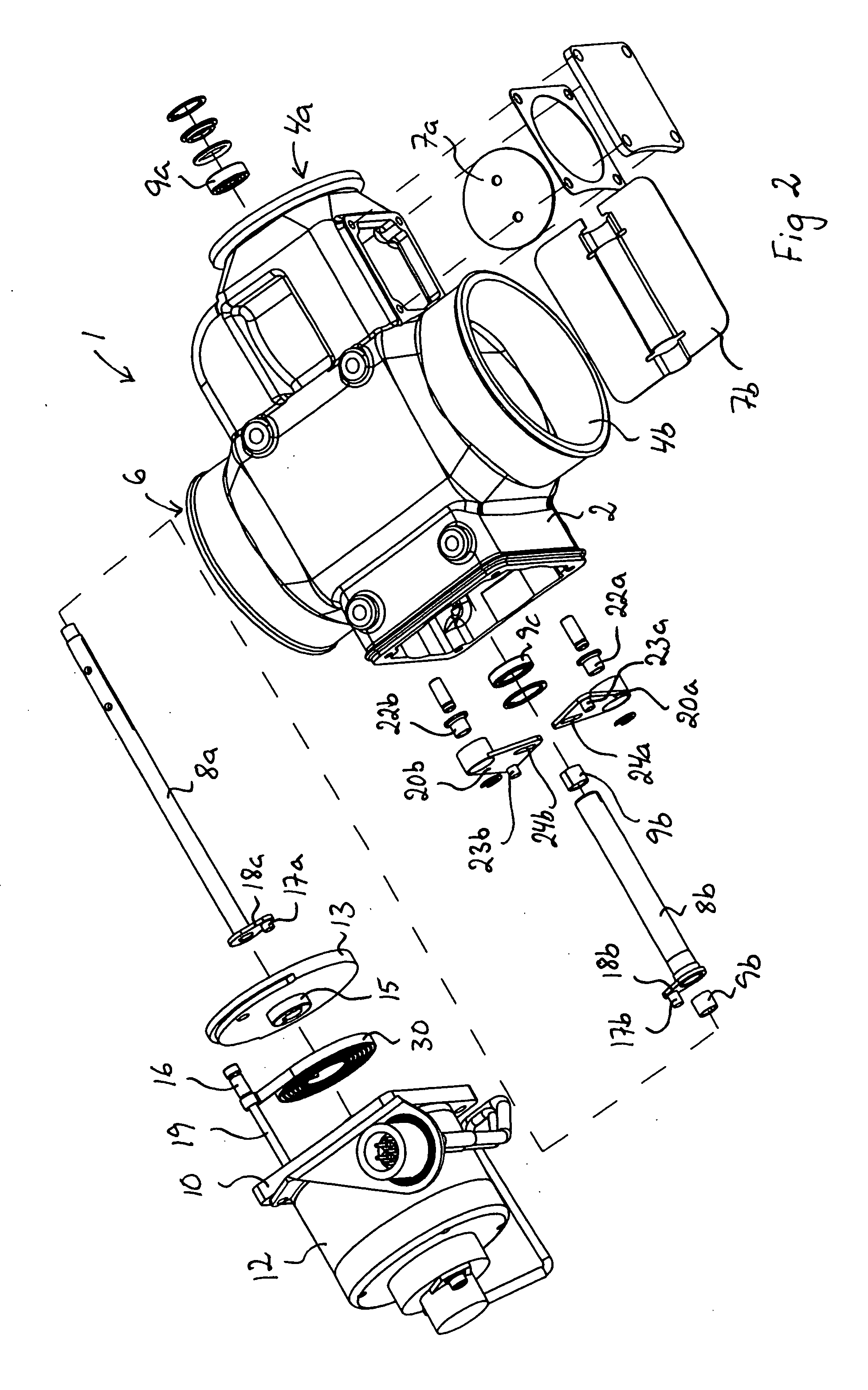
[0016] A valve device 1 according to the present invention is illustrated in FIG. 1-4. This valve device 1 comprises a valve housing 2 with a first flow channel 3a and a second flow channel 3b. The first flow channel 3a is intended to receive a fluid entering the valve device via a first inlet opening 4a of the valve housing, and the second flow channel 3b is intended to receive a fluid entering the valve device via a second inlet opening 4b of the valve housing. The flow channels 3a, 3b are at their downstream ends connected to a common channel 5, which extends further on to an outlet opening 6 of the valve housing. Fluid entering the valve housing via the inlet openings 4a, 4b will consequently be brought together and mixed after the passage through the flow channels 3a, 3b so as to thereafter flow out of the valve housing via the outlet opening 6.

[0017] A first damper 7a, which is fixed to a first damper shaft 8a, is arranged in the first flow channel 3a, and a second damper 7b, ...

second embodiment

[0025] A valve device 101 according to the present invention is illustrated in FIG. 5-7. This valve device 101 comprises a valve housing 103 with a first flow channel 103a and a second flow channel 103b. The first flow channel 103a is intended to receive a fluid entering the valve device via a first inlet opening 104a of the valve housing, and the second flow channel 103b is intended to receive a fluid entering the valve device via a second inlet opening 104b of the valve housing. The flow channels 103a, 103b are at their downstream ends connected to a common channel 105, which extends further on to an outlet opening 106 of the valve housing. Fluid entering the valve housing via the inlet openings 104a, 104b will consequently be brought together and mixed after the passage through the flow channels 103a, 103b so as to thereafter flow out of the valve housing via the outlet opening 106.

[0026] A first damper 107a, which is fixed to a first damper shaft 108a, is arranged in the first f...


PUM


Abstract

The invention relates to a valve device comprising a valve housing (2) with a first and a second flow channel (3a, 3b), and a first and second damper shaft (8a, 8b), which are rotatable relative to the valve housing (2). A first damper (7a) is arranged in the first flow channel (3a) fixed to the first damper shaft (8a) and a second damper (7b) is arranged in the second flow channel (3b) fixed to the second damper shaft (8b). A rotatable regulating member (13) is arranged to control the rotational position of the damper shafts (8a, 8b) via two motion transfer members (20a, 20b), the respective motion transfer member (20a, 20b) being in engagement with a guiding (21) of the regulating member (13) so that the rotational position of the motion transfer member and thereby the rotational position of the associated damper shaft (8a, 8b) is controlled by the rotational position of the regulating member via this guiding (21).

Description

FIELD OF THE INVENTION AND PRIOR ART [0001] The present invention relates to a valve device according to the preamble of claim 1. [0002] A valve device according to the preamble of claim 1 is previously known from the patent publication WO 00 / 28203 A1. This known valve device is intended to be included in an EGR system (EGR=Exhaust Gas Recirculation) of a combustion engine so as to regulate the relation between the amount of fresh air supplied to the combustion engine from the inlet air channel of the combustion engine and the amount of recirculated exhaust gases supplied to the combustion engine from the recirculation conduit of the EGR system. This mixture adjusted by means of the valve device is supplied to the air intake of the engine. The valve device is in this case controlled by means of an EGR control device in dependence on inter alia the rotational speed and the load of the combustion engine. The valve device known from WO 00 / 28203 A1 comprises a first inlet channel intend...

Claims


Application Information

Patent Timeline
IPC IPC(8): F02D9/02F02D9/10F02MF02M25/07F16F9/34F16K1/22F16K11/052F16K11/14F16K31/04
CPCF02D9/1065F02D9/109F02D2009/0276F02M25/0724F02M25/0773F16K31/045F02M25/0793F02M25/0798F16K1/221Y02T10/121F16K31/043F02M25/0786F16K11/165F02M26/21F02M26/51F02M26/54F02M26/64F02M26/70Y10T137/86743Y10T137/87129Y10T137/87692F16K11/052
Inventor BLOMQUIST, MICAELBERGSTROM, STEFANERICSON, URBANTHORSELL, MAGNUS
Owner STT EMTEC AB
Why Eureka
Try Eureka