Multiple component mixing head

Inactive Publication Date: 2005-11-03
HENNECKE
View PDF9 Cites 2 Cited by
  • Summary
  • Abstract
  • Description
  • Claims
  • Application Information

AI Technical Summary

Benefits of technology

[0015] The present invention thus provides a mixing head for simultaneous mixing of a plurality of components, by which an outflow of mixture with laminar flow and free of bubbles can b

Problems solved by technology

Otherwise, the outflowing reaction mixture may not completely fill the cross-section of the outlet channel, which results in disruptive turbulence and in air entering the mixture.
However, as a result of the very small diameters of the mixing chambers as known in the art, and in particular with small outgoing quantities, a structural problem arises: it is then the case that for example six control grooves have to be arranged spatially parallel next to one another on the limited periphery of the control slide means, while still leaving space for the seal between the control grooves.
As a consequence of this problem, in the case of the known constructions the grooves become too narrow and the loss in pressure during recirculation be

Method used


Image

  • Multiple component mixing head
  • Multiple component mixing head
  • Multiple component mixing head

Examples


Embodiment Construction

[0022] The present invention will now be described for purposes of illustration and not limitation. Except in the operating examples, or where otherwise indicated, all numbers expressing quantities, percentages and so forth in the specification are to be understood as being modified in all instances by the term “about.”

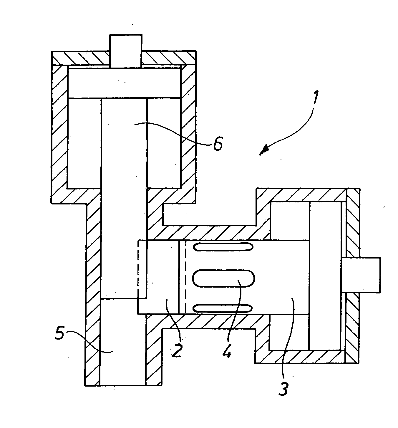
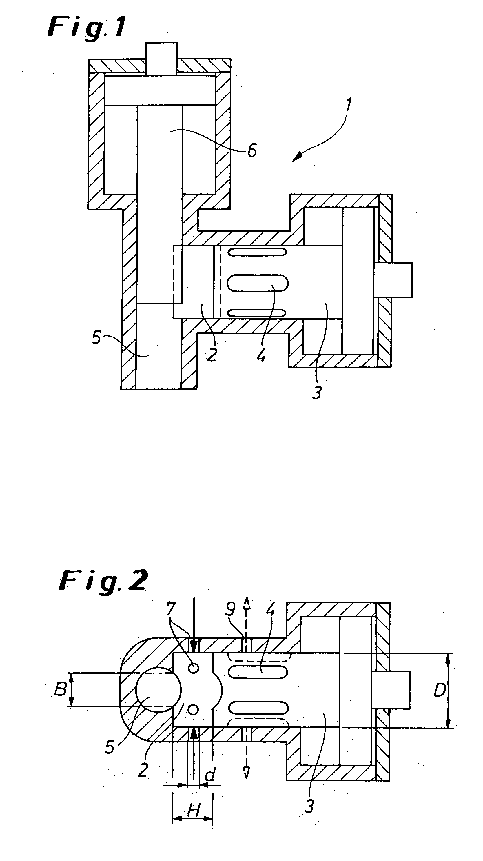
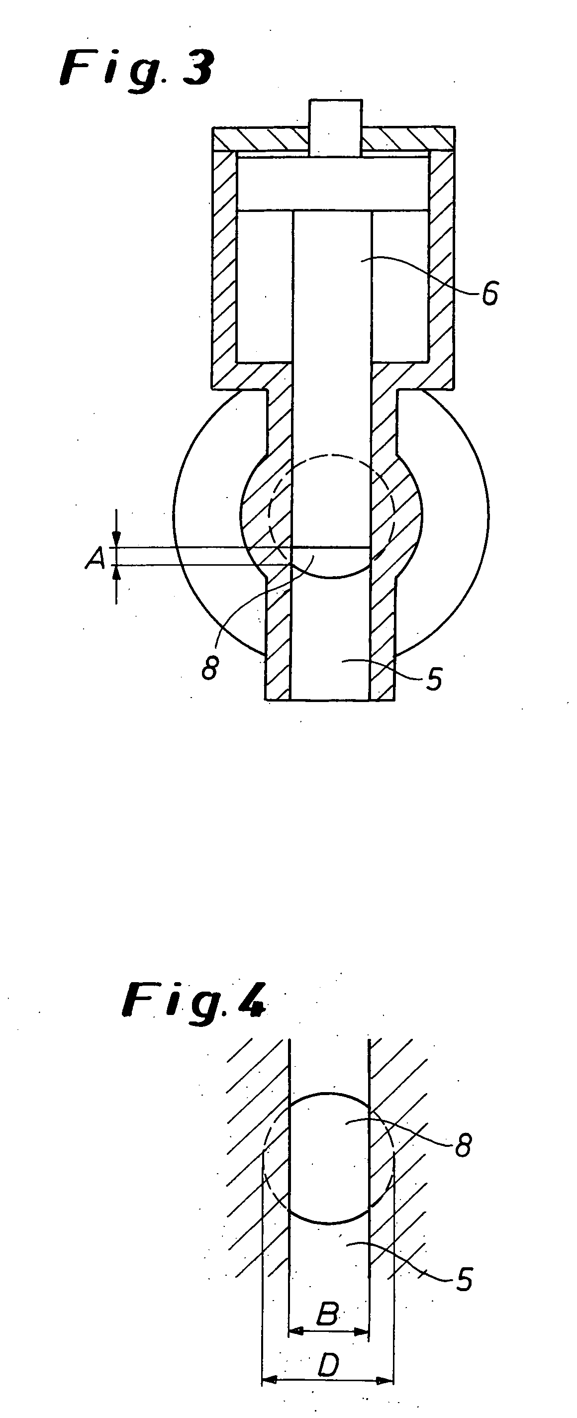
[0023] The invention relates to a mixing head for mixing at least one polyol component and at least one isocyanate component and where appropriate, additives, to form a polyurethane reaction mixture, containing a cylindrical mixing chamber on which at least two inlet nozzles for the respective components are arranged, distributed over the periphery, a control slide means which is arranged in the mixing chamber movably in an axial direction between a front position and a rear position, and on the periphery whereof grooves are arranged, with the components being able when the control slide means is in the front position to enter the grooves through the inlet nozzles, fl...


PUM

PropertyMeasurementUnit
Angleaaaaaaaaaa
Angleaaaaaaaaaa
Lengthaaaaaaaaaa

Abstract

The invention relates to a mixing head and to a method of mixing at least one polyol component and at least one isocyanate component and where appropriate additives, to form a polyurethane reaction mixture.

Description

FIELD OF THE INVENTION [0001] The present invention relates to a mixing head for mixing at least one polyol component and at least one isocyanate component and where appropriate, additives, to form a polyurethane reaction mixture. BACKGROUND OF THE INVENTION [0002] When polyurethane moldings are made, conventionally for each shot a plurality of components (isocyanate, polyol, propellant, additives, etc.) are metered into a mixing chamber, mixed there and fed to a mold. For this mixing task, multiple component mixing heads are used, enabling the various components to be mixed at the same time. [0003] Multiple component mixing heads of this kind conventionally have a cylindrical mixing chamber which is closed at one end and into which the various components are injected by way of inlet nozzles arranged on the periphery. In this arrangement, the inlet nozzles are conventionally arranged on a circular line so that the component jets entering the mixing chamber meet and are mixed. Genera...

Claims


Application Information

Patent Timeline
IPC IPC(8): B01F23/00B29B7/76B29C45/18B29C67/24
CPCB29C67/246B29B7/7668B29B7/7694Y10T137/4351Y10T137/8766Y10T137/87668B29B7/76
Inventor WIRTH, JURGENRAFFEL, REINER
Owner HENNECKE
Why Eureka
Try Eureka